- 您现在的位置:买卖IC网 > PDF目录17639 > MCP1404-E/SO (Microchip Technology)IC MOSFET DVR 4.5A DUAL 16SOIC PDF资料下载
参数资料
| 型号: | MCP1404-E/SO |
| 厂商: | Microchip Technology |
| 文件页数: | 10/22页 |
| 文件大小: | 0K |
| 描述: | IC MOSFET DVR 4.5A DUAL 16SOIC |
| 标准包装: | 47 |
| 配置: | 低端 |
| 输入类型: | 非反相 |
| 延迟时间: | 40ns |
| 电流 - 峰: | 4.5A |
| 配置数: | 2 |
| 输出数: | 2 |
| 电源电压: | 4.5 V ~ 18 V |
| 工作温度: | -40°C ~ 125°C |
| 安装类型: | 表面贴装 |
| 封装/外壳: | 16-SOIC(0.295",7.50mm 宽) |
| 供应商设备封装: | 16-SOIC |
| 包装: | 管件 |
�� �
�
�MCP1403/4/5�
�4.0�
�4.1�
�APPLICATION� INFORMATION�
�General� Information�
�MOSFET� drivers� are� high-speed,� high� current� devices�
�V� DD� =� 18V�
�which� are� intended� to� source/sink� high� peak� currents� to�
�charge/discharge� the� gate� capacitance� of� external�
�MOSFETs� or� IGBTs.� In� high� frequency� switching�
�power� supplies,� the� PWM� controller� may� not� have� the�
�drive� capability� to� directly� drive� the� power� MOSFET.� A�
�MOSFET� driver� like� the� MCP1403/4/5� family� can� be�
�used� to� provide� additional� source/sink� current�
�capability.�
�Input�
�Input�
�1� μF�
�0.1� μF�
�Ceramic�
�Output�
�C� L� =� 2200� pF�
�4.2�
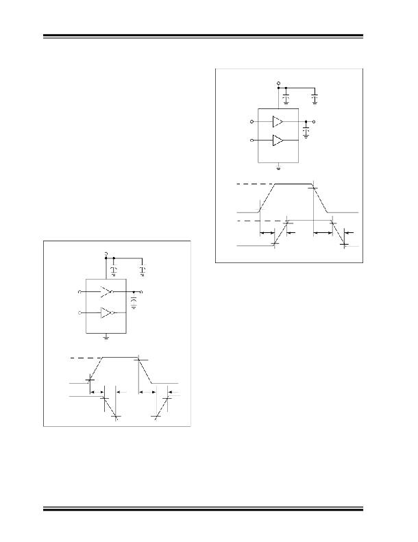
�MOSFET� Driver� Timing�
�MCP1404�
�(1/2� MCP1405)�
�The� ability� of� a� MOSFET� driver� to� transition� from� a� fully�
�off� state� to� a� fully� on� state� are� characterized� by� the� driv-�
�ers� rise� time� (t� R� ),� fall� time� (t� F� ),� and� propagation� delays�
�(t� D1� and� t� D2� ).� The� MCP1403/4/5� family� of� drivers� can�
�typically� charge� and� discharge� a� 2200� pF� load� capaci-�
�+5V�
�Input�
�90%�
�tance� in� 15� ns� along� with� a� typical� matched� propaga-�
�tion� delay� of� 40� ns.� Figure� 4-1� and� Figure� 4-2� show� the�
�test� circuit� and� timing� waveform� used� to� verify� the�
�MCP1403/4/5� timing.�
�0V�
�18V�
�Output�
�10%�
�t� D1� 90%�
�t� R�
�t� D2�
�90%�
�t� F�
�V� DD� =� 18V�
�0V�
�10%�
�10%�
�1� μF�
�0.1� μF�
�Ceramic�
�FIGURE� 4-2:�
�Waveform.�
�Non-Inverting� Driver� Timing�
�Input�
�Input�
�+5V�
�MCP1403�
�(1/2� MCP1405)�
�Output�
�C� L� =� 2200� pF�
�90%�
�4.3� Decoupling� Capacitors�
�Careful� layout� and� decoupling� capacitors� are� highly�
�recommended� when� using� MOSFET� drivers.� Large�
�currents� are� required� to� charge� and� discharge�
�capacitive� loads� quickly.� For� example,� 2.5A� are� needed�
�to� charge� a� 2200� pF� load� with� 18V� in� 16� ns.�
�To� operate� the� MOSFET� driver� over� a� wide� frequency�
�range� with� low� supply� impedance� a� ceramic� and� low�
�ESR� film� capacitor� are� recommended� to� be� placed� in�
�Input�
�0V�
�18V�
�Output�
�10%�
�t� D1�
�90%�
�t� F�
�t� D2�
�t� R�
�90%�
�parallel� between� the� driver� V� DD� and� GND.� A� 1.0� μF� low�
�ESR� film� capacitor� and� a� 0.1� μF� ceramic� capacitor�
�placed� between� V� DD� and� GND� pins� should� be� used.�
�These� capacitors� should� be� placed� close� to� the� driver�
�to� minimized� circuit� board� parasitics� and� provide� a� local�
�source� for� the� required� current.�
�0V�
�10%�
�10%�
�4.4�
�PCB� Layout� Considerations�
�FIGURE� 4-1:�
�Waveform.�
�DS22022B-page� 10�
�Inverting� Driver� Timing�
�Proper� PCB� layout� is� important� in� a� high� current,� fast�
�switching� circuit� to� provide� proper� device� operation� and�
�robustness� of� design.� PCB� trace� loop� area� and�
�inductance� should� be� minimized� by� the� use� of� ground�
�planes� or� trace� under� MOSFET� gate� drive� signals,�
�separate� analog� and� power� grounds,� and� local� driver�
�decoupling.�
�?� 2007� Microchip� Technology� Inc.�
�相关PDF资料 |
PDF描述 |
|---|---|
| HCM49-5.0688MABJ-UT | CRYSTAL 5.0688 MHZ 18PF SMD |
| B32529C1684K | CAP FILM 0.68UF 100VDC RADIAL |
| UB225SKG035F | SWITCH PUSH DPDT 0.4VA 28V |
| B32021A3682K | CAP FILM 6800PF 1.5KVDC RADIAL |
| YB26SKW01-GB | SWITCH PUSHBUTTON DPDT 3A 125V |
相关代理商/技术参数 |
参数描述 |
|---|---|
| MCP1404T-E/MF | 功能描述:功率驱动器IC 4.5A Dual MOSFET Drvr RoHS:否 制造商:Micrel 产品:MOSFET Gate Drivers 类型:Low Cost High or Low Side MOSFET Driver 上升时间: 下降时间: 电源电压-最大:30 V 电源电压-最小:2.75 V 电源电流: 最大功率耗散: 最大工作温度:+ 85 C 安装风格:SMD/SMT 封装 / 箱体:SOIC-8 封装:Tube |
| MCP1404T-E/P | 制造商:MICROCHIP 制造商全称:Microchip Technology 功能描述:4.5A Dual High-Speed Power MOSFET Drivers |
| MCP1404T-E/SN | 功能描述:功率驱动器IC 4.5A Dual MOSFET Drvr RoHS:否 制造商:Micrel 产品:MOSFET Gate Drivers 类型:Low Cost High or Low Side MOSFET Driver 上升时间: 下降时间: 电源电压-最大:30 V 电源电压-最小:2.75 V 电源电流: 最大功率耗散: 最大工作温度:+ 85 C 安装风格:SMD/SMT 封装 / 箱体:SOIC-8 封装:Tube |
| MCP1404T-E/SO | 功能描述:功率驱动器IC 4.5A Dual MOSFET Driver RoHS:否 制造商:Micrel 产品:MOSFET Gate Drivers 类型:Low Cost High or Low Side MOSFET Driver 上升时间: 下降时间: 电源电压-最大:30 V 电源电压-最小:2.75 V 电源电流: 最大功率耗散: 最大工作温度:+ 85 C 安装风格:SMD/SMT 封装 / 箱体:SOIC-8 封装:Tube |
| MCP1405 | 制造商:MICROCHIP 制造商全称:Microchip Technology 功能描述:4.5A Dual High-Speed Power MOSFET Drivers |
发布紧急采购,3分钟左右您将得到回复。