参数资料
| 型号: | MCP215XDM |
| 厂商: | Microchip Technology |
| 文件页数: | 48/58页 |
| 文件大小: | 0K |
| 描述: | BOARD DEMO FOR MCP215X |
| 产品培训模块: | PIC18 J Series MCU Overview |
| 标准包装: | 1 |
| 主要目的: | 接口,IrDA |
| 嵌入式: | 是,MCU,8 位 |
| 已用 IC / 零件: | MCP2150,MCP2155 |
| 主要属性: | 带 PIC18F MCU 的 IrDA 控制器 |
| 次要属性: | 设置为数据记录器,带 LCD,GUI,用于 EEPROM 的插口,可电池供电 |
| 已供物品: | 板,电源 |
| 产品目录页面: | 685 (CN2011-ZH PDF) |
| 相关产品: | MCP2155T-I/SO-ND - IC IRDA PROTOCOL CONTRLR 18-SOIC MCP2150T-I/SO-ND - IC IRDA STD CONTROLLER 18SOIC MCP2150T-I/SS-ND - IC IRDA STD CONTROLLER 20SSOP MCP2155T-I/SS-ND - IC IRDA PROTOCOL CONTRLR 20-SSOP MCP2155-I/SO-ND - IC IRDA PROTOCOL CTRLR 18SOIC MCP2155-I/P-ND - IC IRDA PROTOCOL CTRLR 18DIP MCP2155-I/SS-ND - IC IRDA PROTOCOL CTRLR 20SSOP MCP2150-I/SS-ND - IC IRDA STD CONTROLLER 20SSOP MCP2150-I/SO-ND - IC IRDA STD CONTROLLER 18SOIC MCP2150-I/P-ND - IC IRDA STD CONTROLLER 18DIP |
| 其它名称: | MCP215XDMR MCP215XDMR-ND |
第1页第2页第3页第4页第5页第6页第7页第8页第9页第10页第11页第12页第13页第14页第15页第16页第17页第18页第19页第20页第21页第22页第23页第24页第25页第26页第27页第28页第29页第30页第31页第32页第33页第34页第35页第36页第37页第38页第39页第40页第41页第42页第43页第44页第45页第46页第47页当前第48页第49页第50页第51页第52页第53页第54页第55页第56页第57页第58页
�� �
�
�MCP215X� Data� Logger� Demo� Board� User’s� Guide�
�2.5.6�
�Using� the� Integrated� Optical� Transceiver� (U5)�
�To� use� the� integrated� optical� transceiver,� it� must� be� electrically� powered� and� connected�
�to� the� system.� Connecting� the� integrated� optical� transceiver� is� done� by:�
�1.� Shorting� Jumper� JP7.�
�(this� connects� V� DD� to� the� integrated� optical� transceiver� (U5))�
�2.� Shorting� Jumper� JP1.�
�If� jumper� JP1� is� removed,� ensure� that� the� short� between� two� pins� (on� bottom-side�
�of� board)� is� present.�
�3.� Shorting� Jumper� JP2.�
�If� jumper� JP2� is� removed,� ensure� that� the� short� between� two� pins� (on� bottom-side�
�of� board)� is� present.�
�Now� the� integrated� optical� transceiver� should� be� operational.�
�2.5.7�
�Using� a� Discrete� Optical� Transceiver� Daughter� Board� via�
�Headers� J1� and� J5�
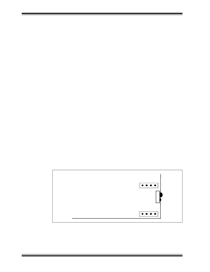
�To� use� an� alternative� optical� transceiver,� a� daughter� board� can� be� connected� to� the�
�MCP215X� Data� Logger� Demo� Board� via� the� connection� header� of� J1� and� J5� (see�
�Figure� 2-13).� The� integrated� optical� transceiver� on� the� MCP215X� Data� Logger� Demo�
�Board� must� be� electrically� removed� from� the� system.� The� following� explains� how� to�
�accomplish� this:�
�1.� Remove� Jumper� on� JP7� (this� removes� V� DD� from� the� integrated� optical�
�transceiver� (U5)).�
�2.� Remove� Jumper� on� JP1.�
�If� jumper� is� removed,� ensure� that� the� short� between� two� pins� (on� bottom� side� of�
�board)� has� been� cut.�
�3.� Remove� Jumper� on� JP2.�
�If� jumper� is� removed,� ensure� that� the� short� between� two� pins� (on� bottom� side� of�
�board)� has� been� cut.�
�4.� Plug� the� discrete� optical� transceiver� board� into� Header� J1� and� J5.�
�Now� the� optical� transceiver� daughter� board� should� be� operational.�
�DS51516A-page� 44�
�FIGURE� 2-13:�
�OPTICAL� TRANSCEIVER� DAUGHTER� BOARD� INTERFACE�
�HEADER� (J1� AND� J5)�
�J1�
�J5�
�?� 2004� Microchip� Technology� Inc.�
�相关PDF资料 |
PDF描述 |
|---|---|
| MCP23X08EV | BOARD EVALUATION FOR MCP23X08 |
| MCP23X17EV | BOARD EVAL FOR MCP23X17 |
| MCP2515DM-PTPLS | BOARD DAUGHTER PICTAIL MCP2515 |
| MCP3905EV | BOARD DEMO FOR MCP3905 |
| MCP402XEV | BOARD EVAL FOR MCP402X |
相关代理商/技术参数 |
参数描述 |
|---|---|
| MCP2200 | 制造商:MICROCHIP 制造商全称:Microchip Technology 功能描述:USB 2.0 to UART Protocol Converter with GPIO |
| MCP2200_11 | 制造商:MICROCHIP 制造商全称:Microchip Technology 功能描述:USB 2.0 to UART Protocol Converter with GPIO |
| MCP2200_13 | 制造商:MICROCHIP 制造商全称:Microchip Technology 功能描述:USB 2.0 to UART Protocol Converter with GPIO |
| MCP-220-00001-01 | 制造商:Supermicro Computer Inc 功能描述:HOT-SWAPPABLE HARD DRIVE TRAY BLACK - Bulk |
| MCP-220-00001-03 | 制造商:SUPER MICRO COMPUTER, INC. 功能描述:HOT-SWAP 3.5" DRIVE TRAY, SILVER - Bulk |
发布紧急采购,3分钟左右您将得到回复。