- 您现在的位置:买卖IC网 > PDF目录132988 > MCP2510T-I/P 2 CHANNEL(S), 1M bps, LOCAL AREA NETWORK CONTROLLER, PDIP18 PDF资料下载
参数资料
| 型号: | MCP2510T-I/P |
| 元件分类: | 微控制器/微处理器 |
| 英文描述: | 2 CHANNEL(S), 1M bps, LOCAL AREA NETWORK CONTROLLER, PDIP18 |
| 封装: | 0.300 INCH, PLASTIC, DIP-18 |
| 文件页数: | 23/76页 |
| 文件大小: | 1076K |
| 代理商: | MCP2510T-I/P |
第1页第2页第3页第4页第5页第6页第7页第8页第9页第10页第11页第12页第13页第14页第15页第16页第17页第18页第19页第20页第21页第22页当前第23页第24页第25页第26页第27页第28页第29页第30页第31页第32页第33页第34页第35页第36页第37页第38页第39页第40页第41页第42页第43页第44页第45页第46页第47页第48页第49页第50页第51页第52页第53页第54页第55页第56页第57页第58页第59页第60页第61页第62页第63页第64页第65页第66页第67页第68页第69页第70页第71页第72页第73页第74页第75页第76页
1999 Microchip Technology Inc.
Preliminary
DS21291C-page 3
MCP2510
1.0
DEVICE FUNCTIONALITY
1.1
Overview
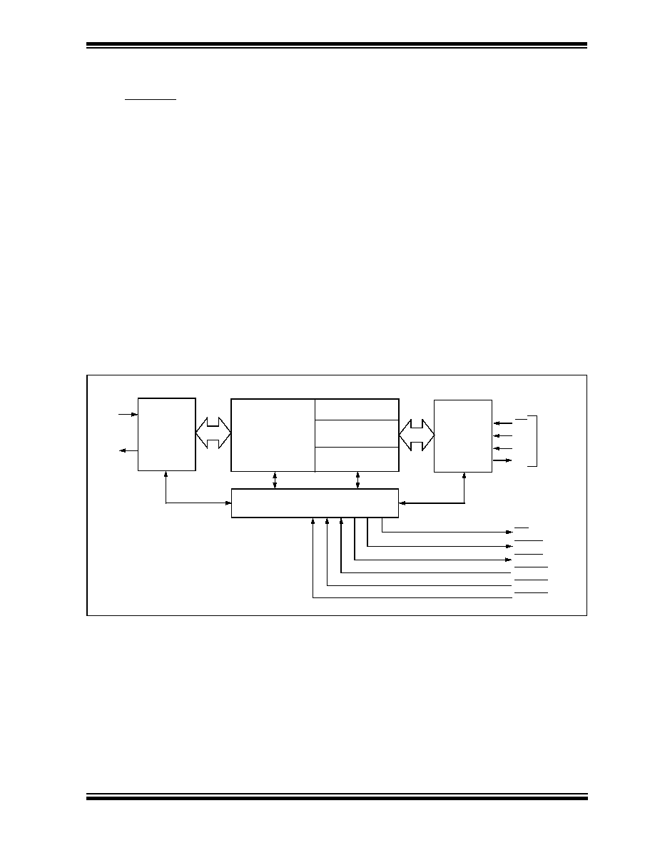
The MCP2510 is a stand-alone CAN controller devel-
oped to simplify applications that require interfacing
with a CAN bus. A simple block diagram of the
MCP2510 is shown in Figure 1-1. The device consists
of three main blocks:
1.
the CAN protocol engine,
2.
the control logic and SRAM registers that are
used to configure the device and its operation,
and
3.
the SPI protocol block.
A typical system implementation using the device is
shown in Figure 1-2.
The CAN protocol engine handles all functions for
receiving and transmitting messages on the bus. Mes-
sages are transmitted by first loading the appropriate
message buffer and control registers. Transmission is
initiated by using control register bits, via the SPI inter-
face, or by using the transmit enable pins. Status and
errors can be checked by reading the appropriate reg-
isters. Any message detected on the CAN bus is
checked for errors and then matched against the user
defined filters to see if it should be moved into one of
the two receive buffers.
The MCU interfaces to the device via the SPI interface.
Writing to and reading from all registers is done using
standard SPI read and write commands.
Interrupt pins are provided to allow greater system flex-
ibility. There is one multi-purpose interrupt pin as well
as specific interrupt pins for each of the receive regis-
ters that can be used to indicate when a valid message
has been received and loaded into one of the receive
buffers. Use of the specific interrupt pins is optional,
and the general purpose interrupt pin as well as status
registers (accessed via the SPI interface) can also be
used to determine when a valid message has been
received.
There are also three pins available to initiate immediate
transmission of a message that has been loaded into
one of the three transmit registers. Use of these pins is
optional and initiating message transmission can also
be done by utilizing control registers accessed via the
SPI interface.
Table 1-1 gives a complete list of all of the pins on the
MCP2510.
FIGURE 1-1:
Block Diagram
3 TX
Buffers
2 RX Buffers
Message Assembly
6 Acceptance
Filters
SPI
Interface
Logic
SPI
Bus
INT
Buffer
CS
SCK
SI
SO
CAN
Protocol
Engine
RXCAN
TXCAN
Control Logic
RX0BF
RX1BF
TX0RTS
TX1RTS
TX2RTS
相关PDF资料 |
PDF描述 |
|---|---|
| M34282E2GP | 4-BIT, OTPROM, 4 MHz, MICROCONTROLLER, PDSO20 |
| MSM82C53-2GS-K | 3 TIMER(S), PROGRAMMABLE TIMER, PDSO32 |
| MC68HC05JB4DW | 8-BIT, MROM, 3 MHz, MICROCONTROLLER, PDSO28 |
| MD80C32XXX-12 | 8-BIT, 12 MHz, MICROCONTROLLER, CDIP40 |
| MJ80C52XXX-36MQ | 8-BIT, MROM, 36 MHz, MICROCONTROLLER, QCC44 |
相关代理商/技术参数 |
参数描述 |
|---|---|
| MCP2515 | 制造商:MICROCHIP 制造商全称:Microchip Technology 功能描述:Stand-Alone CAN Controller With SPI Interface |
| MCP2515_12 | 制造商:MICROCHIP 制造商全称:Microchip Technology 功能描述:Stand-Alone CAN Controller with SPI Interface |
| MCP2515DM-BM | 功能描述:网络开发工具 CAN Bus Monitor Demo Board RoHS:否 制造商:Rabbit Semiconductor 产品:Development Kits 类型:Ethernet to Wi-Fi Bridges 工具用于评估:RCM6600W 数据速率:20 Mbps, 40 Mbps 接口类型:802.11 b/g, Ethernet 工作电源电压:3.3 V |
| MCP2515DM-PCTL | 功能描述:网络开发工具 MCP2515 CAN Cont PICtail Demo Brd RoHS:否 制造商:Rabbit Semiconductor 产品:Development Kits 类型:Ethernet to Wi-Fi Bridges 工具用于评估:RCM6600W 数据速率:20 Mbps, 40 Mbps 接口类型:802.11 b/g, Ethernet 工作电源电压:3.3 V |
| MCP2515DM-PTPLS | 功能描述:子卡和OEM板 MCP2515 PICTail Plus Daughtr Brd RoHS:否 制造商:BeagleBoard by CircuitCo 产品:BeagleBone LCD4 Boards 用于:BeagleBone - BB-Bone - Open Source Development Kit |
发布紧急采购,3分钟左右您将得到回复。