- 您现在的位置:买卖IC网 > PDF目录25626 > MF280C51C-36R (ATMEL CORP) 8-BIT, MROM, 36 MHz, MICROCONTROLLER, PQFP44 PDF资料下载
参数资料
| 型号: | MF280C51C-36R |
| 厂商: | ATMEL CORP |
| 元件分类: | 微控制器/微处理器 |
| 英文描述: | 8-BIT, MROM, 36 MHz, MICROCONTROLLER, PQFP44 |
| 封装: | QFP-44 |
| 文件页数: | 6/28页 |
| 文件大小: | 6193K |
| 代理商: | MF280C51C-36R |
第1页第2页第3页第4页第5页当前第6页第7页第8页第9页第10页第11页第12页第13页第14页第15页第16页第17页第18页第19页第20页第21页第22页第23页第24页第25页第26页第27页第28页
14
2467X–AVR–06/11
ATmega128
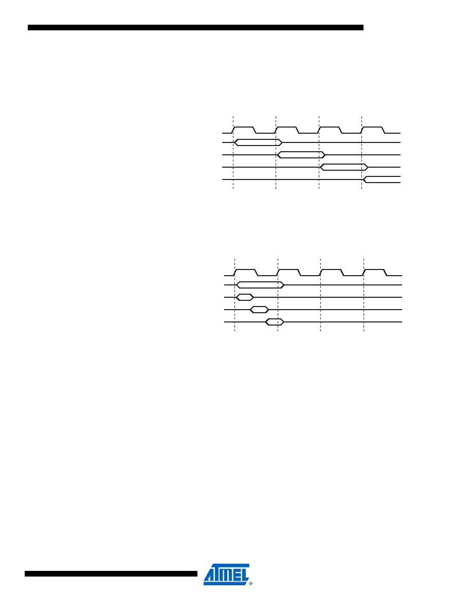
Figure 6 shows the parallel instruction fetches and instruction executions enabled by the Har-
vard architecture and the fast-access Register file concept. This is the basic pipelining concept
to obtain up to 1 MIPS per MHz with the corresponding unique results for functions per cost,
functions per clocks, and functions per power-unit.
Figure 6. The Parallel Instruction Fetches and Instruction Executions
Figure 7 shows the internal timing concept for the Register file. In a single clock cycle an ALU
operation using two register operands is executed, and the result is stored back to the destina-
tion register.
Figure 7. Single Cycle ALU Operation
Reset and
Interrupt Handling
The AVR provides several different interrupt sources. These interrupts and the separate reset
vector each have a separate program vector in the program memory space. All interrupts are
assigned individual enable bits which must be written logic one together with the Global Interrupt
Enable bit in the Status Register in order to enable the interrupt. Depending on the Program
Counter value, interrupts may be automatically disabled when Boot Lock bits BLB02 or BLB12
are programmed. This feature improves software security. See the section “Memory Program-
ming” on page 286 for details.
The lowest addresses in the program memory space are by default defined as the Reset and
Interrupt vectors. The complete list of vectors is shown in “Interrupts” on page 59. The list also
determines the priority levels of the different interrupts. The lower the address the higher is the
priority level. RESET has the highest priority, and next is INT0 – the External Interrupt Request
0. The interrupt vectors can be moved to the start of the boot Flash section by setting the IVSEL
bit in the MCU Control Register (MCUCR). Refer to “Interrupts” on page 59 for more information.
The Reset vector can also be moved to the start of the boot Flash section by programming the
BOOTRST fuse, see “Boot Loader Support – Read-While-Write Self-Programming” on page
When an interrupt occurs, the Global Interrupt Enable I-bit is cleared and all interrupts are dis-
abled. The user software can write logic one to the I-bit to enable nested interrupts. All enabled
interrupts can then interrupt the current interrupt routine. The I-bit is automatically set when a
Return from Interrupt instruction – RETI – is executed.
clk
1st Instruction Fetch
1st Instruction Execute
2nd Instruction Fetch
2nd Instruction Execute
3rd Instruction Fetch
3rd Instruction Execute
4th Instruction Fetch
T1
T2
T3
T4
CPU
Total Execution Time
Register Operands Fetch
ALU Operation Execute
Result Write Back
T1
T2
T3
T4
clk
CPU
相关PDF资料 |
PDF描述 |
|---|---|
| MQ80C52TXXX-16SC | 8-BIT, MROM, 16 MHz, MICROCONTROLLER, CQFP44 |
| MQ80C52XXX-16P883D | 8-BIT, MROM, 16 MHz, MICROCONTROLLER, CQFP44 |
| MQ80C32-20SCD | 8-BIT, 20 MHz, MICROCONTROLLER, CQFP44 |
| MQ80C52TXXX-20/883D | 8-BIT, MROM, 20 MHz, MICROCONTROLLER, CQFP44 |
| MD80C32-30P883 | 8-BIT, 30 MHz, MICROCONTROLLER, CDIP40 |
相关代理商/技术参数 |
参数描述 |
|---|---|
| MF283C151C-12 | 制造商:TEMIC 制造商全称:TEMIC Semiconductors 功能描述:CMOS 0 to 36 MHz Single Chip 8-bit Microcontroller |
| MF283C151C-16 | 制造商:TEMIC 制造商全称:TEMIC Semiconductors 功能描述:CMOS 0 to 36 MHz Single Chip 8-bit Microcontroller |
| MF283C151C-20 | 制造商:TEMIC 制造商全称:TEMIC Semiconductors 功能描述:CMOS 0 to 36 MHz Single Chip 8-bit Microcontroller |
| MF283C151C-25 | 制造商:TEMIC 制造商全称:TEMIC Semiconductors 功能描述:CMOS 0 to 36 MHz Single Chip 8-bit Microcontroller |
| MF283C151C-30 | 制造商:TEMIC 制造商全称:TEMIC Semiconductors 功能描述:CMOS 0 to 36 MHz Single Chip 8-bit Microcontroller |
发布紧急采购,3分钟左右您将得到回复。