- 您现在的位置:买卖IC网 > PDF目录16916 > MIC2044-2BTS TR (Micrel Inc)IC DISTRIBUTION SW SGL 16-TSSOP PDF资料下载
参数资料
| 型号: | MIC2044-2BTS TR |
| 厂商: | Micrel Inc |
| 文件页数: | 11/15页 |
| 文件大小: | 0K |
| 描述: | IC DISTRIBUTION SW SGL 16-TSSOP |
| 标准包装: | 2,500 |
| 类型: | 高端开关 |
| 输出数: | 1 |
| Rds(开): | 30 毫欧 |
| 内部开关: | 是 |
| 电流限制: | 可调 |
| 输入电压: | 0.8 V ~ 5.5 V |
| 工作温度: | -40°C ~ 85°C |
| 安装类型: | 表面贴装 |
| 封装/外壳: | 16-TSSOP(0.173",4.40mm 宽) |
| 供应商设备封装: | 16-TSSOP |
| 包装: | 带卷 (TR) |
| 其它名称: | MIC2044-2BTSTR MIC2044-2BTSTR-ND |
�� �
�
�MIC2044/2045�
�Functional� Description�
�The� MIC2044� and� MIC2045� are� high-side� N-Channel� switches�
�equipped� with� programmable� current� limit� up� to� 6A� for� use� in�
�general� purpose� power� distribution� applications.� The� switches,�
�available� with� active-high� or� active-low� enable� inputs,� provide�
�output� slew-rate� control� and� circuit� protection� via� thermal�
�shutdown� and� an� optional� output� latch� during� overcurrent�
�conditions.�
�Input� and� Output�
�VBIAS� supplies� power� to� the� internal� circuitry� of� the� switch�
�and� must� be� present� for� the� switch� to� operate.� VIN� is� con-�
�nected� to� the� drain� of� the� output� MOSFET� and� sources� power�
�to� the� switched� load.� VIN� must� be� less� than� or� equal� to� VBIAS.�
�VOUT� is� the� source� terminal� of� the� output� MOSFET� and�
�attaches� to� the� load.� In� a� typical� circuit,� current� flows� from� VIN�
�to� VOUT� toward� the� load.� If� VOUT� is� greater� than� VIN,� current�
�will� flow� from� VOUT� to� VIN� since� the� switch� is� bi-directional�
�Micrel�
�Programmable� Current� Limit�
�The� MIC2044/45� is� designed� to� prevent� damage� to� the�
�external� load� by� limiting� the� maximum� amount� of� current� it�
�can� draw.� The� current� limit� is� programmed� by� an� external�
�resistor� (R� SET� )� connected� from� ILIM� (Pin� 6)� to� ground� and�
�becomes� active� when� the� output� voltage� is� at� least� 200mV�
�below� the� voltage� at� the� input� to� the� device.� The� limiting�
�current� value� is� defined� by� the� current� limit� factor� (CLF)�
�divided� by� R� SET� ,� and� the� MIC2044/45� will� limit� from� 1A� to� 6A�
�with� a� set� point� accuracy� of� ±� 21%.� In� programming� the�
�nominal� current� limit,� the� value� of� R� SET� is� determined� using�
�the� following� equation:�
�CLF� (� 380A� � ?� )�
�R� SET� =� =� (1)�
�I� LIMIT� I� LIMIT�
�And� given� the� ±� 21%� tolerance� of� the� current� limit� factor� (CLF),�
�the� external� resistor� is� bound� by:�
�when� the� device� is� enabled.� When� disabled� (OFF),� the� switch�
�50� ?� ≤� R� SET� ≤� 460� ?�
�(2)�
�will� block� current� flow� from� either� direction.�
�Enable� Input�
�Enable,� the� ON/OFF� control� for� the� output� switch,� is� a� digital�
�input� available� as� an� active-high� (–1)� or� active-low� (–2)�
�signal.� The� EN� pin,� referenced� to� approximately� 0.5� � VBIAS,�
�must� be� driven� to� a� clearly� defined� logic� high� or� logic� low.�
�Failure� to� observe� this� requirement,� or� allowing� EN� to� float,�
�will� cause� the� MIC2044/45� to� exhibit� unpredictable� behavior.�
�EN� should� not� be� allowed� to� go� negative� with� respect� to�
�ground,� nor� allowed� to� exceed� VBIAS.� Failure� to� adhere� to�
�these� conditions� may� result� in� damage� to� the� device.�
�Undervoltage� Lockout�
�When� the� switch� is� enabled,� undervoltage� lockout� (UVLO)�
�monitors� the� input� voltage,� V� IN� ,� and� prevents� the� output�
�MOSFET� from� turning� on� until� V� IN� exceeds� a� predetermined�
�level,� nominally� set� at� 1.45V.� The� UVLO� threshold� is� adjust-�
�able� and� can� be� varied� by� applying� an� external� resistor� divider�
�to� the� UVLOIN� pin� from� VIN� to� GND.� The� resistive� divider�
�network� is� required� when� the� input� voltage� is� below� 1.5V.� The�
�UVLO� threshold� is� internally� preset� to� 1.45V� if� the� UVLOIN�
�pin� is� left� open.� See� “Applications� Information.”�
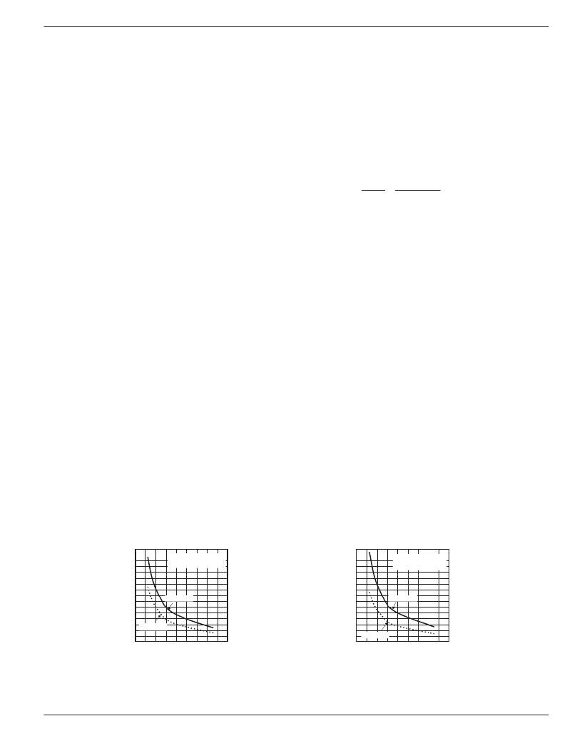
�Current� Limit�
�The� graphs� below� (Figure� 3)� display� the� current� limit� factor�
�characteristic� over� the� full� temperature� range� at� the� indicated�
�voltage.� These� curves� can� be� used� as� a� point� of� reference� in�
�determining� the� maximum� variation� in� the� device’s� current�
�limit� over� the� full� temperature� range.� For� example:� With� V� IN�
�=� V� BIAS� =� 3.0V� and� a� nominal� 4A� current� limit� (R� SET� =� 95� ?� ),�
�the� low� and� high� current� limit� settings� for� the� MIC2044/45�
�would� be� 3.15A� and� 4.85A,� respectively,� as� shown� on� the� 3V�
�graph� using� the� 95� ?� reference� point.�
�When� current� limiting� occurs,� the� MIC2044� and� MIC2045�
�respond� differently.� Upon� first� reaching� the� limiting� current�
�both� devices� restrict� current� flow,� allowing� the� load� voltage� to�
�drop� below� V� IN� .� If� the� V� IN� to� V� OUT� differential� voltage� exceeds�
�200mV,� then� a� fault� condition� is� declared� and� the� fault� delay�
�timer� is� started.� If� the� fault� condition� persists� longer� than� the�
�delay� period,� typically� 32ms,� then� the� /FAULT� output� asserts�
�low.� At� this� point,� the� MIC2044� will� continue� to� supply� current�
�to� the� load� at� the� limiting� value� (I� LIMIT� ),� whereas� the� MIC2045�
�will� latch� off� its� output.�
�Current� Limit�
�8�
�7�
�6�
�5�
�4�
�3�
�2�
�1�
�0�
�vs.� R� SET�
�–40� °� C� to� +85� °� C�
�V� IN� =� V� BIAS� =� 3V,� 5V�
�CLF� (HI)�
�CLF (LO)�
�0� 50� 100� 150� 200� 250� 300� 350� 400� 450�
�R� SET� (� ?� )�
�8�
�7�
�6�
�5�
�4�
�3�
�2�
�1�
�0�
�vs.� R� SET�
�–40� °� C� to� +85� °� C�
�V� IN� =� V� BIAS� =� 1.6V�
�CLF� (HI)�
�CLF (LO)�
�0� 50� 100� 150� 200� 250� 300� 350� 400� 450�
�R� SET� (� ?� )�
�Figure� 3.� Current� Limit� Factor�
�January� 2005�
�11�
�MIC2044/2045�
�相关PDF资料 |
PDF描述 |
|---|---|
| 222A152-100-0 | BOOT MOLDED |
| 382LX473M050B062VS | CAP ALUM 47000UF 50V 20% SNAP |
| MIC2045-1BTS | IC DISTRIBUTION SW SGL 16-TSSOP |
| 0982660108 | CBL 10POS 0.5MM JMPR TYPE D 7" |
| LAR2W221MELA40 | CAP ALUM 220UF 450V 20% SNAP |
相关代理商/技术参数 |
参数描述 |
|---|---|
| MIC2044-2YTS | 功能描述:电源开关 IC - USB 22 mohm Low Voltage Switch - Lead Free RoHS:否 制造商:Micrel 电源电压-最小:2.7 V 电源电压-最大:5.5 V 最大工作温度:+ 85 C 最小工作温度:- 40 C 封装 / 箱体:SOIC-8 封装:Tube |
| MIC2044-2YTS TR | 功能描述:电源开关 IC - USB 23 mohm Low Voltage Switch - Lead Free RoHS:否 制造商:Micrel 电源电压-最小:2.7 V 电源电压-最大:5.5 V 最大工作温度:+ 85 C 最小工作温度:- 40 C 封装 / 箱体:SOIC-8 封装:Tube |
| MIC2045 | 制造商:MICREL 制造商全称:Micrel Semiconductor 功能描述:Single Channel, High Current, Low Voltage, Protected Power Distribution Switch |
| MIC2045-1BTS | 功能描述:IC DISTRIBUTION SW SGL 16-TSSOP RoHS:否 类别:集成电路 (IC) >> PMIC - 电源分配开关 系列:- 特色产品:XRP252 Switches 标准包装:1 系列:- 类型:高端开关 输出数:2 Rds(开):140 毫欧 内部开关:是 电流限制:1.15A 输入电压:1.75 V ~ 5.5 V 工作温度:-40°C ~ 85°C 安装类型:表面贴装 封装/外壳:10-WFDFN 裸露焊盘 供应商设备封装:10-TDFN(3x3) 包装:Digi-Reel® 其它名称:1016-1691-6 |
| MIC2045-1BTS TR | 功能描述:IC DISTRIBUTION SW SGL 16-TSSOP RoHS:否 类别:集成电路 (IC) >> PMIC - 电源分配开关 系列:- 特色产品:XRP252 Switches 标准包装:1 系列:- 类型:高端开关 输出数:2 Rds(开):140 毫欧 内部开关:是 电流限制:1.15A 输入电压:1.75 V ~ 5.5 V 工作温度:-40°C ~ 85°C 安装类型:表面贴装 封装/外壳:10-WFDFN 裸露焊盘 供应商设备封装:10-TDFN(3x3) 包装:Digi-Reel® 其它名称:1016-1691-6 |
发布紧急采购,3分钟左右您将得到回复。