- 您现在的位置:买卖IC网 > PDF目录17062 > MIC2099-1YMT TR (Micrel Inc)IC DISTRIBUTION SWITCH PDF资料下载
参数资料
| 型号: | MIC2099-1YMT TR |
| 厂商: | Micrel Inc |
| 文件页数: | 17/25页 |
| 文件大小: | 0K |
| 描述: | IC DISTRIBUTION SWITCH |
| 标准包装: | 1 |
| 系列: | * |
| 其它名称: | 576-3783-6 |
�� �
�
�Micrel,� Inc.�
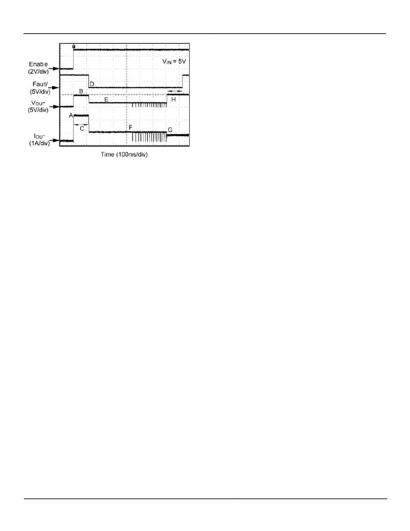
�Figure� 1.� MIC2097� Kickstart� Operation�
�Figure� 1� Label� Key:�
�A.� The� MIC2097� is� enabled� into� an� excessive� load�
�(slew-rate� limiting� not� visible� at� this� time� scale)� The�
�initial� current� surge� is� limited� by� either� the� overall�
�circuit� resistance� and� power-supply� compliance,� or�
�the� secondary� current� limit,� whichever� is� less.�
�B.� R� ON� of� the� power� FET� increases� due� to� internal�
�heating.�
�C.� Kickstart� period.�
�D.� Current� limiting� initiated.� FAULT/� goes� low.�
�E.� V� OUT� is� non-zero� (load� is� heavy,� but� not� a� dead� short�
�where� V� OUT� =� 0V.� Limiting� response� will� be� the� same�
�for� dead� shorts).�
�F.� Thermal� shutdown� followed� by� thermal� cycling.�
�MIC2095/97/98/99�
�pull-up� resistor.� FAULT/� may� be� tied� to� a� pull-up� voltage�
�source� which� is� less� than� or� equal� to� V� IN� .�
�Soft-Start� Control�
�Large� capacitive� loads� can� create� significant� inrush�
�current� surges� when� charged� through� the� current� limiting�
�switch.� When� the� switch� is� enabled,� the� built-in� soft-start�
�limits� the� initial� inrush� current� by� slowly� turning� on� the�
�output.�
�Power� Dissipation� and� Thermal� Shutdown�
�Thermal� shutdown� is� used� to� protect� the� current� limiting�
�switch� from� damage� should� the� die� temperature� exceed�
�a� safe� operating� temperature.� Thermal� shutdown� shuts�
�off� the� output� MOSFET� and� asserts� the� FAULT/� output� if�
�the� die� temperature� reaches� 145°C� (typical).�
�The� switch� will� automatically� resume� operation� when� the�
�die� temperature� cools� down� to� 135°C.� If� resumed�
�operation� results� in� reheating� of� the� die,� another�
�shutdown� cycle� will� occur� and� the� switch� will� continue�
�cycling� between� ON� and� OFF� states� until� the� reason� for�
�the� overcurrent� condition� has� been� resolved.�
�Depending� on� PCB� layout,� package� type,� ambient�
�temperature,� etc.,� hundreds� of� milliseconds� may� elapse�
�from� the� time� a� fault� occurs� to� the� time� the� output�
�MOSFET� will� be� shut� off.� This� delay� is� caused� because�
�of� the� time� it� takes� for� the� die� to� heat� after� the� fault�
�condition� occurs.�
�Power� dissipation� depends� on� several� factors� such� as�
�the� load,� PCB� layout,� ambient� temperature,� and� supply�
�voltage.� Calculation� of� power� dissipation� can� be�
�accomplished� by� the� following� equation:�
�P� D� =� R� DS(ON)� � (� I� OUT� )�
�G.� Excessive� load� released,� normal� load� remains.�
�MIC2097� drops� out� of� current� limiting.�
�H.� FAULT/� delay� period� followed� by� FAULT/� going�
�HIGH.�
�2�
�Eq.� 2�
�Enable� Input�
�The� ENABLE� pin� is� a� logic� level� compatible� input� which�
�To� relate� this� to� junction� temperature,� the� following�
�equation� can� be� used:�
�turns� on� or� off� the� main� MOSFET� switch.� There� are� two�
�versions� of� each� device.� The� ?� 1� version� has� an� active�
�high� (ENABLE)� and� the� ?� 2� version� has� an� active� low�
�T� J� =� P� D� ×� R� θ� (J� -� A)� +� T� A�
�Eq.� 3�
�(ENABLE/).�
�Fault� Output�
�The� FAULT/� is� an� N-channel� open-drain� output,� which� is�
�asserted� (LOW� true)� when� the� device� either� begins�
�current� limiting� or� enters� thermal� shutdown.� The� FAULT/�
�signal� asserts� after� a� brief� delay� period� in� order� to� filter�
�out� very� brief� over� current� conditions.� After� an� over-�
�current� or� over-temperature� fault� clears,� the� FAULT/� pin�
�remains� asserted� (low)� for� the� delay� period.�
�The� FAULT/output� is� open-drain� and� must� be� pulled�
�HIGH� with� an� external� resistor.� The� FAULT/� signal� may�
�be� wire-OR’d� with� other� similar� outputs,� sharing� a� single�
�Where� T� J� =� junction� temperature,� T� A� =� ambient�
�temperature,� and� R� θ� (J-A)� is� the� thermal� resistance� of� the�
�package.�
�In� normal� operation,� excessive� switch� heating� is� most�
�often� caused� by� an� output� short� circuit.� If� the� output� is�
�shorted,� when� the� switch� is� enabled,� the� switch� limits� the�
�output� current� to� the� maximum� value.� The� heat�
�generated� by� the� power� dissipation� of� the� switch�
�continuously� limiting� the� current� may� exceed� the�
�package� and� PCB’s� ability� to� cool� the� device� and� the�
�switch� will� shut� down� and� signal� a� fault� condition.� Please�
�see� the� Fault� Output� description� in� the� previous� page� for�
�more� details� on� the� FAULT/� output.� After� the� switch�
�August� 2011�
�17�
�M9999-080211-C�
�相关PDF资料 |
PDF描述 |
|---|---|
| RCA10DRMI-S288 | CONN EDGECARD 20POS .125 EXTEND |
| HBM11DSEN-S243 | CONN EDGECARD 22POS .156 EYELET |
| AD9772A-EBZ | BOARD EVAL FOR AD9772A |
| ECE-V1VA101UP | CAP ALUM 100UF 35V 20% SMD |
| 94SVP107X0016F8 | CAP ALUM 100UF 16V 20% SMD |
相关代理商/技术参数 |
参数描述 |
|---|---|
| MIC2099-2YMT | 制造商:MICREL 制造商全称:Micrel Semiconductor 功能描述:Current-Limiting Power Distribution Switches |
| MIC2099-2YMT TR | 功能描述:电源开关 IC - USB Power Distribution Switch with Programmable Current Limit RoHS:否 制造商:Micrel 电源电压-最小:2.7 V 电源电压-最大:5.5 V 最大工作温度:+ 85 C 最小工作温度:- 40 C 封装 / 箱体:SOIC-8 封装:Tube |
| MIC2099-2YMT-TR | 功能描述:IC DISTRIBUTION SWITCH 制造商:microchip technology 系列:- 包装:剪切带(CT) 零件状态:停产 开关类型:通用 输出数:1 比率 - 输入:输出:1:1 输出配置:高端 输出类型:P 通道 接口:开/关 电压 - 负载:2.5 V ~ 5.5 V 电压 - 电源(Vcc/Vdd):不需要 电流 - 输出(最大值):1.1A 导通电阻(典型值):170 毫欧 输入类型:非反相 特性:压摆率受控型 故障保护:限流(可调),超温,UVLO 工作温度:-40°C ~ 125°C (TJ) 封装/外壳:6-UFDFN 裸露焊盘 供应商器件封装:6-TDFN(1.6x1.6) 标准包装:1 |
| MIC20XX | 制造商:MICREL 制造商全称:Micrel Semiconductor 功能描述:Fixed and Adjustable Current Limiting Power Distribution Switches |
| MIC20XX_1108 | 制造商:MICREL 制造商全称:Micrel Semiconductor 功能描述:Fixed and Adjustable Current Limiting Power Distribution Switches |
发布紧急采购,3分钟左右您将得到回复。