- 您现在的位置:买卖IC网 > PDF目录13493 > MIC2204BML TR (Micrel Inc)IC REG BUCK SYNC ADJ 0.6A 10MLF PDF资料下载
参数资料
| 型号: | MIC2204BML TR |
| 厂商: | Micrel Inc |
| 文件页数: | 8/11页 |
| 文件大小: | 0K |
| 描述: | IC REG BUCK SYNC ADJ 0.6A 10MLF |
| 标准包装: | 5,000 |
| 类型: | 降压(降压) |
| 输出类型: | 可调式 |
| 输出数: | 1 |
| 输出电压: | 可调至 1V |
| 输入电压: | 2.3 V ~ 5.5 V |
| PWM 型: | 电压模式 |
| 频率 - 开关: | 2MHz |
| 电流 - 输出: | 600mA |
| 同步整流器: | 是 |
| 工作温度: | -40°C ~ 125°C |
| 安装类型: | 表面贴装 |
| 封装/外壳: | 10-VFDFN 裸露焊盘,10-MLF? |
| 包装: | 带卷 (TR) |
| 供应商设备封装: | 10-MLF?(3x3) |
| 其它名称: | MIC2204BMLTR |
�� �
�
�Efficiency� %� =� ?� OUT� OUT� ?� � 100�
�MIC2204�
�Applications� Information�
�Input� Capacitor�
�A� minimum� 1� μ� F� ceramic� is� recommended� on� the� VIN� pin� for�
�bypassing.� X5R� or� X7R� dielectrics� are� recommended� for� the�
�input� capacitor.� Y5V� dielectrics� are� not� recommended:� they�
�lose� most� of� their� capacitance� over� temperature� and� also�
�become� resistive� at� high� frequencies.� This� reduces� their�
�ability� to� filter� out� high� frequency� noise.�
�Output� Capacitor�
�The� MIC2204� was� designed� specifically� for� the� use� of� a� 4.7� μ� F�
�ceramic� output� capacitor.� The� output� capacitor� requires�
�either� an� X7R� or� X5R� dielectric.� Y5V� and� Z5U� dielectric�
�capacitors,� aside� from� the� undesirable� effect� of� their� wide�
�variation� in� capacitance� over� temperature,� become� resistive�
�at� high� frequencies.� Using� Y5V� or� Z5U� capacitors� will� cause�
�instability� in� the� MIC2204.� For� output� voltages� less� than� 1.6V,�
�a� 10� μ� F� capacitor� may� be� required� for� stability.� See� the�
�“Compensation”� section� for� more� detail.�
�Total� output� capacitance� should� not� exceed� 15� μ� F.� Large�
�values� of� capacitance� can� cause� current� limit� to� engage�
�during� start-up.� If� larger� than� 15� μ� F� is� required,� a� feed-forward�
�capacitor� from� the� output� to� the� feedback� node� should� be�
�used� to� slow� the� start-up� time.�
�Inductor� Selection�
�Inductor� selection� will� be� determined� by� the� following� (not�
�necessarily� in� the� order� of� importance):�
�?� Inductance�
�?� Rated� current� value�
�?� Size� requirements�
�?� DC� resistance� (DCR)�
�The� MIC2204� is� designed� for� use� with� a� 4.7� μ� H� inductor.�
�Maximum� current� ratings� of� the� inductor� are� generally� given�
�in� two� methods:� permissible� DC� current� and� saturation� cur-�
�rent.� Permissible� DC� current� can� be� rated� either� for� a� 40� °� C�
�temperature� rise� or� a� 10%� loss� in� inductance.� Ensure� the�
�inductor� selected� can� handle� the� maximum� operating� cur-�
�rent.� When� saturation� current� is� specified,� make� sure� that�
�there� is� enough� margin� that� the� peak� current� will� not� saturate�
�the� inductor.�
�Micrel,� Inc.�
�The� size� requirements� refer� to� the� area� and� height� require-�
�ments� that� are� necessary� to� fit� a� particular� design.� Please�
�refer� to� the� inductor� dimensions� on� their� data� sheet.�
�DC� resistance� is� also� important.� While� DCR� is� inversely�
�proportional� to� size,� DCR� can� represent� a� significant� effi-�
�ciency� loss.� Refer� to� the� “� Efficiency� Considerations� ”� below�
�for� a� more� detailed� description.�
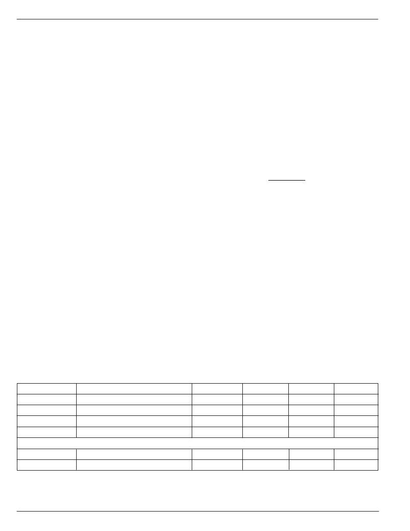
�Table� 1� below� shows� a� list� of� recommended� 4.7� μ� H� inductors�
�by� manufacturer,� part� number� and� key� specifications.�
�Bias� Capacitor�
�A� small� 10nF� ceramic� capacitor� is� required� to� bypass� the�
�BIAS� pin.� The� use� of� low� ESR� ceramics� provides� improved�
�filtering� for� the� bias� supply.�
�Efficiency� Considerations�
�Efficiency� is� defined� as� the� amount� of� useful� output� power,�
�divided� by� the� amount� of� power� consumed.�
�?� V� � I� ?�
�?� V� IN� � I� IN� ?�
�Maintaining� high-efficiency� serves� two� purposes.� It� reduces�
�power� dissipation� in� the� power� supply,� reducing� the� need� for�
�heat� sinks� and� thermal� design� considerations� and� it� reduces�
�consumption� of� current� for� battery� powered� applications.�
�Reduced� current� draw� from� a� battery� increases� the� devices�
�operating� time,� critical� in� handheld� devices.�
�There� are� two� loss� terms� in� switching� converters:� DC� losses�
�and� switching� losses.� DC� losses� are� simply� the� power� dissi-�
�pation� of� I� 2� R.� For� example,� power� is� dissipated� in� the� high-�
�side� switch� during� the� on� cycle,� where� power� loss� is� equal� to�
�the� high-side� MOSFET� R� DSON� multiplied� by� the� Switch�
�Current� 2� .� During� the� off� cycle,� the� low-side� N-Channel�
�MOSFET� conducts,� also� dissipating� power.� Device� operating�
�current� also� reduces� efficiency.� The� product� of� the� quiescent�
�(operating)� current� and� the� supply� voltage� is� another� DC� loss.�
�The� current� required� to� drive� the� gates� on� and� off� at� a� constant�
�2MHz� frequency� and� the� switching� transitions� make� up� the�
�switching� losses.�
�Manufacturer�
�Sumida�
�Murata�
�Murata�
�Coilcraft�
�P/N�
�CDRH2D18-4R7�
�LQH43CN4R7M01�
�LQH32CN4R7M11�
�1008PS-472M�
�H(mm)�
�2�
�2.6�
�2.2�
�2.74�
�W(mm)�
�3.2�
�3.2�
�2.7�
�3.8�
�L(mm)�
�3.2�
�4.6�
�3.4�
�3.8�
�DCR(m� ?� )�
�81�
�150�
�195�
�350�
�Low� Profile�
�TDK�
�Sumida�
�LDR5610T-4R7MR90�
�CMD4D06�
�1�
�0.8�
�5.2�
�6.3�
�5.8�
�5.8�
�240�
�216�
�Table� 1.� Component� Selection� Table�
�M9999-042205�
�8�
�April� 2005�
�相关PDF资料 |
PDF描述 |
|---|---|
| MAX6770TASD1+T | IC REG LINEAR 3.3V/ADJ 8-TDFN |
| RCC49DREI | CONN EDGECARD 98POS .100 EYELET |
| VI-J3K-EW-F3 | CONVERTER MOD DC/DC 40V 100W |
| RYM10DTMN-S273 | CONN EDGECARD 20POS R/A .156 SLD |
| UPJ0J561MPD6TD | CAP ALUM 560UF 6.3V 20% RADIAL |
相关代理商/技术参数 |
参数描述 |
|---|---|
| MIC2204BMM | 功能描述:IC REG BUCK SYNC ADJ 0.6A 10MSOP RoHS:否 类别:集成电路 (IC) >> PMIC - 稳压器 - DC DC 开关稳压器 系列:- 标准包装:20 系列:SIMPLE SWITCHER® 类型:降压(降压) 输出类型:固定 输出数:1 输出电压:12V 输入电压:4 V ~ 60 V PWM 型:电压模式 频率 - 开关:52kHz 电流 - 输出:1A 同步整流器:无 工作温度:-40°C ~ 125°C 安装类型:通孔 封装/外壳:16-DIP(0.300",7.62mm) 包装:管件 供应商设备封装:16-DIP 其它名称:*LM2575HVN-12LM2575HVN-12 |
| MIC2204BMM TR | 功能描述:IC REG BUCK SYNC ADJ 0.6A 10MSOP RoHS:否 类别:集成电路 (IC) >> PMIC - 稳压器 - DC DC 开关稳压器 系列:- 标准包装:20 系列:SIMPLE SWITCHER® 类型:降压(降压) 输出类型:固定 输出数:1 输出电压:12V 输入电压:4 V ~ 60 V PWM 型:电压模式 频率 - 开关:52kHz 电流 - 输出:1A 同步整流器:无 工作温度:-40°C ~ 125°C 安装类型:通孔 封装/外壳:16-DIP(0.300",7.62mm) 包装:管件 供应商设备封装:16-DIP 其它名称:*LM2575HVN-12LM2575HVN-12 |
| MIC2204YML | 功能描述:直流/直流开关调节器 2MHz Synchronous Buck Regulator - Pb Free Finish RoHS:否 制造商:International Rectifier 最大输入电压:21 V 开关频率:1.5 MHz 输出电压:0.5 V to 0.86 V 输出电流:4 A 输出端数量: 最大工作温度: 安装风格:SMD/SMT 封装 / 箱体:PQFN 4 x 5 |
| MIC2204YML TR | 功能描述:直流/直流开关调节器 2MHz Synchronous Buck Regulator (Lead Free) RoHS:否 制造商:International Rectifier 最大输入电压:21 V 开关频率:1.5 MHz 输出电压:0.5 V to 0.86 V 输出电流:4 A 输出端数量: 最大工作温度: 安装风格:SMD/SMT 封装 / 箱体:PQFN 4 x 5 |
| MIC2204YML-TR | 功能描述:Buck Switching Regulator IC Positive Adjustable 1V 1 Output 600mA 10-VFDFN Exposed Pad, 10-MLF? 制造商:microchip technology 系列:- 包装:剪切带(CT) 零件状态:停产 功能:降压 输出配置:正 拓扑:降压 输出类型:可调式 输出数:1 电压 - 输入(最小值):2.3V 电压 - 输入(最大值):5.5V 电压 - 输出(最小值/固定):1V 电压 - 输出(最大值):5.5V 电流 - 输出:600mA 频率 - 开关:2MHz 同步整流器:是 工作温度:-40°C ~ 125°C (TJ) 安装类型:表面贴装 封装/外壳:10-VFDFN 裸露焊盘,10-MLF? 供应商器件封装:10-MLF?(3x3) 标准包装:1 |
发布紧急采购,3分钟左右您将得到回复。