- 您现在的位置:买卖IC网 > PDF目录14468 > MIC2204YMM (Micrel Inc)IC REG BUCK SYNC ADJ 0.6A 10MSOP PDF资料下载
参数资料
| 型号: | MIC2204YMM |
| 厂商: | Micrel Inc |
| 文件页数: | 9/11页 |
| 文件大小: | 0K |
| 描述: | IC REG BUCK SYNC ADJ 0.6A 10MSOP |
| 标准包装: | 100 |
| 类型: | 降压(降压) |
| 输出类型: | 可调式 |
| 输出数: | 1 |
| 输出电压: | 可调至 1V |
| 输入电压: | 2.3 V ~ 5.5 V |
| PWM 型: | 电压模式 |
| 频率 - 开关: | 2MHz |
| 电流 - 输出: | 600mA |
| 同步整流器: | 是 |
| 工作温度: | -40°C ~ 125°C |
| 安装类型: | 表面贴装 |
| 封装/外壳: | 10-TFSOP,10-MSOP(0.118",3.00mm 宽) |
| 包装: | 管件 |
| 供应商设备封装: | 10-MSOP |
| 产品目录页面: | 1092 (CN2011-ZH PDF) |
| 其它名称: | 576-1721-5 MIC2204YMM-ND |
�� �
�
�MIC2204�
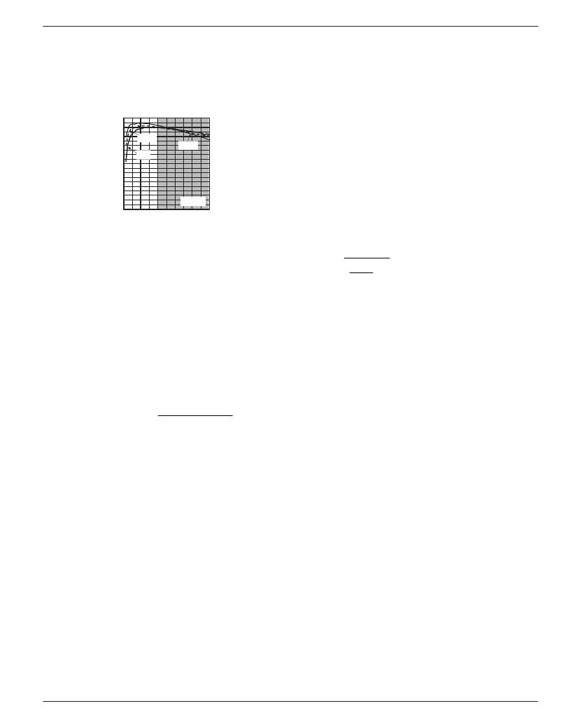
�Figure� 2� shows� an� efficiency� curve.� On� the� non-shaded�
�portion,� from� 0� to� 200mA,� efficiency� losses� are� dominated� by�
�quiescent� current� losses,� gate� drive� and� transition� losses.� In�
�this� case,� lower� supply� voltages� yield� greater� efficiency� in� that�
�they� require� less� current� to� drive� the� MOSFETs� and� have�
�reduced� input� power� consumption.�
�Micrel,� Inc.�
�ing� output� voltage� regulation.� With� a� typical� gain� bandwidth� of�
�200kHz,� the� MIC2204� is� capable� of� extremely� fast� transient�
�responses.�
�The� MIC2204� is� designed� to� be� stable� with� a� 4.7� μ� H� inductor�
�and� a� 4.7� μ� F� ceramic� (X5R)� output� capacitor� for� output�
�voltages� greater� than� 1.6V.� For� output� voltages� less� than�
�100�
�95�
�Efficiency�
�vs.� Output� Current�
�1.6V,� a� 10� μ� F� capacitor� is� required.� Also,� when� a� feed� forward�
�capacitor� is� used,� the� gain� bandwidth� is� increased� to� unity�
�gain.� This� will� also� require� increasing� the� output� capacitor� to�
�90�
�85�
�80�
�75�
�70�
�65�
�60�
�4.2V� IN�
�5V� IN�
�3.6V� IN�
�10� μ� F.�
�Feedback�
�The� MIC2204� provides� a� feedback� pin� to� adjust� the� output�
�voltage� to� the� desired� level.� This� pin� connects� internally� to� an�
�error� amplifier.� The� error� amplifier� then� compares� the� voltage�
�55�
�50�
�0�
�3.3V� OUT�
�100� 200� 300� 400� 500�
�at� the� feedback� to� the� internal� 1V� reference� voltage� and�
�adjusts� the� output� voltage� to� maintain� regulation.� To� calculate�
�?� V� OUT�
�±� 1� ?�
�?� V�
�V� OUT� OUT�
�?� V� OUT� OUT� +� L� PD� ?� ?� ?�
�Efficiency� Loss� =� ?� 1±� ?� ?� ?� ×� 100�
�?� ?�
�OUTPUT CURRENT (A)�
�Figure� 2.�
�On� the� shaded� region,� 200mA� to� 500mA,� efficiency� loss� is�
�dominated� by� MOSFET� R� DSON� and� inductor� losses.� Higher�
�input� supply� voltages� will� increase� the� Gate-to-Source� thresh-�
�old� on� the� internal� MOSFETs,� reducing� the� internal� R� DSON� .�
�This� improves� efficiency� by� reducing� DC� losses� in� the� device.�
�All� but� the� inductor� losses� are� inherent� to� the� device,� making�
�inductor� selection� even� more� critical� in� efficiency� calcula-�
�tions.� As� the� inductors� are� reduced� in� size,� the� DC� resistance�
�(DCR)� can� become� quite� significant.� The� DCR� losses� can� be�
�calculated� as� follows:�
�L� PD� =I� OUT2� x� DCR�
�From� that,� the� loss� in� efficiency� due� to� inductor� resistance� can�
�be� calculated� as� follows:�
�?� ?� � I� ?� ?�
�� I�
�Efficiency� loss� due� to� DCR� is� minimal� at� light� loads� and� gains�
�significance� as� the� load� is� increased.� Inductor� selection�
�becomes� a� trade-off� between� efficiency� and� size� in� this� case.�
�Compensation�
�The� MIC2204� is� an� internally� compensated,� voltage-mode�
�buck� regulator.� Voltage� mode� is� achieved� by� creating� an�
�internal� 2MHz� ramp� signal� and� using� the� output� of� the� error�
�amplifier� to� pulsewidth� modulate� the� switch� node,� maintain-�
�the� resistor� divider� network� for� the� desired� output� is� as�
�follows:�
�R1�
�R2� =�
�?�
�?� REF� ?�
�Where� V� REF� is� 1.0V� and� V� OUT� is� the� desired� output� voltage.�
�A� 10k� ?� or� lower� resistor� value� from� the� output� to� the� feedback�
�is� recommended.� Larger� resistor� values� require� an� additional�
�capacitor� (feed-forward)� from� the� output� to� the� feedback.� The�
�large� high-side� resistor� value� and� the� parasitic� capacitance�
�on� the� feedback� pin� (~10pF)� can� cause� an� additional� pole� in�
�the� loop.� The� additional� pole� can� create� a� phase� loss� at�
�high-frequency.� This� phase� loss� degrades� transient� response�
�by� reducing� phase� margin.� Adding� feed-forward� capacitance�
�negates� the� parasitic� capacitive� effects� of� the� feedback� pin.�
�A� minimum� 1000pF� capacitor� is� recommended� for� feed-�
�forward� capacitance.�
�Also,� large� feedback� resistor� values� increase� the� impedance,�
�making� the� feedback� node� more� susceptible� to� noise� pick-up.�
�A� feed-forward� capacitor� would� also� reduce� noise� pick-up� by�
�providing� a� low� impedance� path� to� the� output.�
�When� using� a� feed-forward� capacitor,� the� gain� bandwidth� of�
�the� device� reaches� unity� gain� at� high-frequency.� Therefore,�
�output� capacitance� will� need� to� be� increased� to� a� minimum�
�10� μ� F.� For� more� information� on� output� capacitor� selection� for�
�stability,� see� the� “Compensation� ”� section.�
�April� 2005�
�9�
�M9999-042205�
�相关PDF资料 |
PDF描述 |
|---|---|
| VE-J7L-EX-B1 | CONVERTER MOD DC/DC 28V 75W |
| VI-BWR-EX-F1 | CONVERTER MOD DC/DC 7.5V 75W |
| VE-J74-EX-B1 | CONVERTER MOD DC/DC 48V 75W |
| VI-BWR-EW-F4 | CONVERTER MOD DC/DC 7.5V 100W |
| SP6644EU-L | IC REG BOOST SYNC 3.3V/ADJ 8MSOP |
相关代理商/技术参数 |
参数描述 |
|---|---|
| MIC2204YMM TR | 功能描述:直流/直流开关调节器 2MHz Synchronous Buck Regulator (Lead Free) RoHS:否 制造商:International Rectifier 最大输入电压:21 V 开关频率:1.5 MHz 输出电压:0.5 V to 0.86 V 输出电流:4 A 输出端数量: 最大工作温度: 安装风格:SMD/SMT 封装 / 箱体:PQFN 4 x 5 |
| MIC2204YMM-TR | 功能描述:Buck Switching Regulator IC Positive Adjustable 1V 1 Output 600mA 10-TFSOP, 10-MSOP (0.118", 3.00mm Width) 制造商:microchip technology 系列:- 包装:剪切带(CT) 零件状态:停产 功能:降压 输出配置:正 拓扑:降压 输出类型:可调式 输出数:1 电压 - 输入(最小值):2.3V 电压 - 输入(最大值):5.5V 电压 - 输出(最小值/固定):1V 电压 - 输出(最大值):5.5V 电流 - 输出:600mA 频率 - 开关:2MHz 同步整流器:是 工作温度:-40°C ~ 125°C (TJ) 安装类型:表面贴装 封装/外壳:10-TFSOP,10-MSOP(0.118",3.00mm 宽) 供应商器件封装:10-MSOP 标准包装:1 |
| MIC2205 | 制造商:MICREL 制造商全称:Micrel Semiconductor 功能描述:2MHz PWM Synchronous Buck Regulator with LDO Standby Mode |
| MIC2205_06 | 制造商:MICREL 制造商全称:Micrel Semiconductor 功能描述:2MHz PWM Synchronous Buck Regulator with LDO Standby Mode |
| MIC2205-1.38YML | 制造商:MICREL 制造商全称:Micrel Semiconductor 功能描述:2MHz PWM Synchronous Buck Regulator with LDO Standby Mode |
发布紧急采购,3分钟左右您将得到回复。