- 您现在的位置:买卖IC网 > PDF目录20774 > MIC3230YTSE (Micrel Inc)IC LED DRVR HP CONS CURR 16TSSOP PDF资料下载
参数资料
| 型号: | MIC3230YTSE |
| 厂商: | Micrel Inc |
| 文件页数: | 10/19页 |
| 文件大小: | 0K |
| 描述: | IC LED DRVR HP CONS CURR 16TSSOP |
| 标准包装: | 94 |
| 恒定电流: | 是 |
| 拓扑: | PWM,升压(升压) |
| 输出数: | 1 |
| 内部驱动器: | 无 |
| 类型 - 主要: | 通用 |
| 频率: | 100kHz ~ 1MHz |
| 电源电压: | 6 V ~ 45 V |
| 安装类型: | 表面贴装 |
| 封装/外壳: | 16-TSSOP(0.173",4.40mm)裸露焊盘 |
| 供应商设备封装: | 16-EPAD TSSOP |
| 包装: | 管件 |
| 工作温度: | -40°C ~ 125°C |
| 产品目录页面: | 1082 (CN2011-ZH PDF) |
| 其它名称: | 576-3402-5 |
�� �
�
�Micrel,� Inc.�
�Dithering� (MIC3231� Only)�
�The� MIC3231� has� a� feature� which� dithers� the� switching�
�frequency� by� ±12%.� The� purpose� of� this� dithering� is� to� help�
�achieve� a� spread� spectrum� of� the� conducted� EMI� noise.�
�This� can� allow� for� an� overall� reduction� in� noise� emission� by�
�approximately� 10dB.�
�Internal� Gate� Driver�
�External� FETs� are� driven� by� the� MIC323x’s� internal� low�
�impedance� gate� drivers.� These� drivers� are� biased� from� the�
�V� DD� and� have� a� source� resistance� of� 2� ?� and� a� sink�
�resistance� of� 3.5� ?� .�
�V� DD�
�V� DD� is� an� internal� linear� regulator� powered� by� V� IN� and� V� DD�
�is� the� bias� supply� for� the� internal� circuitry� of� the� MIC323x.�
�A� 10μF� ceramic� bypass� capacitor� is� required� at� the� V� DD� pin�
�for� proper� operation.� This� pin� is� for� filtering� only� and� should�
�not� be� utilized� for� operation.�
�Current� Limit�
�The� MIC323x� family� features� a� current� limit� protection�
�feature� to� prevent� any� current� runaway� conditions.� The�
�current� limit� circuitry� monitors� current� on� a� pulse� by� pulse�
�basis.� It� limits� the� current� through� the� inductor� by� sensing�
�the� voltage� across� R� CS� .� When� 0.45V� is� present� at� the� IS�
�pin,� the� pulse� is� truncated.� The� next� pulse� continues� as�
�normally� until� the� IS� pin� reaches� 0.45V� and� it� is� truncated�
�once� again.� This� will� continue� until� the� output� load� is�
�decreased.�
�Select� R� CS� using� Equation� 5:�
�MIC3230/1/2�
�Current� Sense� I� S�
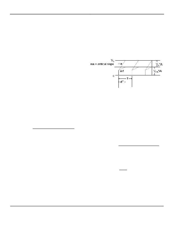
�The� IS� pin� monitors� the� rising� slope� of� the� inductor� current�
�(m1� in� Figure� 5)� and� also� sources� a� ramp� current�
�(250μA/T)� that� flows� through� R� SLC� that� is� used� for� slope�
�compensation.� This� ramp� of� 250μA� per� period,� T,�
�generates� a� ramped� voltage� across� R� SLC� and� is� labeled� V� A�
�in� Figure� 3.� The� signal� at� the� IS� pin� is� the� sum� of� V� CS� +� V� A�
�(as� shown� in� Figure� 3).� The� current� sense� circuitry� and�
�block� diagram� is� displayed� in� Figure� 4.� The� IS� pin� is� also�
�used� as� the� current� limit� (see� the� previous� section� on�
�Current� Limit).�
�Figure� 3.� Slope� Compensation� Waveforms�
�Soft� Start�
�The� boost� switching� convertor� features� a� soft� start� in� order�
�to� power� up� in� a� controlled� manner,� thereby� limiting� the�
�inrush� current� from� the� line� supply.� Without� this� soft� start,�
�the� inrush� current� could� be� too� high� for� the� supply.� To�
�prevent� this,� a� soft� start� delay� can� be� set� using� the�
�compensation� capacitor� (C� COMP� in� Figure� 1).� For� switching�
�to� begin,� the� voltage� on� the� compensation� cap� must� reach�
�(� V�
�)�
�Eq.� (5)�
�R� CS� =�
�0� .� 45�
�OUT� MAX� ?� V� IN� MIN� � D�
�L� � F� SW�
�+� I� L� PK� _� LIMIT�
�about� 0.7V.� Switching� starts� with� the� minimum� duty� cycle�
�and� increases� to� the� final� duty� cycle.� As� the� duty� cycle�
�increases,� V� OUT� will� increase� from� V� IN� to� its� final� value.� A�
�6μA� current� source� charges� the� compensation� capacitor�
�and� the� soft� start� time� can� be� calculated� in� Equation� 7:�
�V� OUT� ?� V� IN� MIN� )� � R� CS�
�Eq.� (6)� R� SLC� =�
�C� COMP� � V� COMP_STEAD� Y_STATE�
�Eq.� (7)� T� SOFTSTART� ≈�
�Where:� V� A� PK� =�
�� R� SLC� � D� � T� and�
�Slope� Compensation�
�The� MIC323x� is� a� peak� current� mode� controller� and�
�requires� slope� compensation.� Slope� compensation� is�
�required� to� maintain� internal� stability� across� all� duty� cycles�
�and� prevent� any� unstable� oscillations.� The� MIC323x� uses�
�slope� compensation� that� is� set� by� an� external� resistor,�
�R� SLC� .� The� ability� to� set� the� proper� slope� compensation�
�through� the� use� of� a� single� external� component� results� in�
�design� flexibility.� This� slope� compensation� resistor,� R� SLC� ,�
�can� be� calculated� using� Equation� 6:�
�MAX�
�L� ×� 250� μ� A� ×� F� SW�
�where� V� IN_MAX� and� V� OUT_MAX� can� be� selected� to� system�
�specifications.�
�6� μ� A�
�V� COMP_STEADY_STATE� is� usually� between� 0.7V� to� 3V,� but� can�
�be� as� high� as� 5V.�
�Eq.� (8)� V� COMP� _� STEADY� _� STATE� =� Ai� � (� V� A� PK� +� Vcs� PK� )�
�I� RAMP�
�T�
�V� CS� PK� =� I� L� _� PK� � R� CS�
�Ai� =� 1.4� V/V�
�D� =� Duty� cycle� (0� to1)�
�T� =� period�
�A� 10nF� ceramic� capacitor� will� make� this� system� stable� at�
�all� operating� conditions.�
�March� 2011�
�10�
�M9999-030311-D�
�相关PDF资料 |
PDF描述 |
|---|---|
| XRP7604EDB-F | IC CONV PWM STP-DWN BUCK 8SOIC |
| GMM02DRYN-S13 | CONN EDGECARD 4POS .156 EXTEND |
| VE-JTF-CW-S | CONVERTER MOD DC/DC 72V 100W |
| GEM28DRUN | CONN EDGECARD 56POS DIP .156 SLD |
| TAJV107K025A | CAP TANT 100UF 25V 10% 2924 |
相关代理商/技术参数 |
参数描述 |
|---|---|
| MIC3230YTSE TR | 功能描述:LED照明驱动器 Boost Driver Controller for High Power LEDs RoHS:否 制造商:STMicroelectronics 输入电压:11.5 V to 23 V 工作频率: 最大电源电流:1.7 mA 输出电流: 最大工作温度: 安装风格:SMD/SMT 封装 / 箱体:SO-16N |
| MIC3231YML | 制造商:MICREL 制造商全称:Micrel Semiconductor 功能描述:Constant Current Boost Controller for Driving High Power LEDs |
| MIC3231YML TR | 功能描述:LED照明驱动器 Boost Driver Controller with Dither for High Power LEDs RoHS:否 制造商:STMicroelectronics 输入电压:11.5 V to 23 V 工作频率: 最大电源电流:1.7 mA 输出电流: 最大工作温度: 安装风格:SMD/SMT 封装 / 箱体:SO-16N |
| MIC3231YML-TR | 功能描述:LED 驱动器 IC 1 输出 DC DC 控制器 升压(升压) PWM 调光 12-MLF?(4x4) 制造商:microchip technology 系列:- 包装:剪切带(CT) 零件状态:停产 类型:DC DC 控制器 拓扑:升压(升压) 内部开关:无 输出数:1 电压 - 供电(最低):6V 电压 -?供电(最高):45V 电压 - 输出:- 电流 - 输出/通道:- 频率:100kHz ~ 1MHz 调光:PWM 应用:照明 工作温度:-40°C ~ 125°C (TJ) 安装类型:表面贴装 封装/外壳:12-VFDFN 裸焊盘,12-MLF? 供应商器件封装:12-MLF?(4x4) 标准包装:1 |
| MIC3231YTSE | 功能描述:LED照明驱动器 Boost Driver Controller with Dither for High Power LEDs RoHS:否 制造商:STMicroelectronics 输入电压:11.5 V to 23 V 工作频率: 最大电源电流:1.7 mA 输出电流: 最大工作温度: 安装风格:SMD/SMT 封装 / 箱体:SO-16N |
发布紧急采购,3分钟左右您将得到回复。