- 您现在的位置:买卖IC网 > PDF目录20457 > MIC4421ABM TR (Micrel Inc)IC DRIVER MOSFET 9A LS 8-SOIC PDF资料下载
参数资料
| 型号: | MIC4421ABM TR |
| 厂商: | Micrel Inc |
| 文件页数: | 9/13页 |
| 文件大小: | 0K |
| 描述: | IC DRIVER MOSFET 9A LS 8-SOIC |
| 标准包装: | 2,500 |
| 配置: | 低端 |
| 输入类型: | 反相 |
| 延迟时间: | 15ns |
| 电流 - 峰: | 9A |
| 配置数: | 1 |
| 输出数: | 1 |
| 电源电压: | 4.5 V ~ 18 V |
| 工作温度: | -40°C ~ 85°C |
| 安装类型: | 表面贴装 |
| 封装/外壳: | 8-SOIC(0.154",3.90mm 宽) |
| 供应商设备封装: | 8-SOIC |
| 包装: | 带卷 (TR) |
| 其它名称: | MIC4421ABMTR MIC4421ABMTR-ND |
�� �
�
�Micrel,� Inc.�
�Input� Stage�
�The� input� voltage� level� of� the� MIC4421A� changes� the�
�V� IN� +18V�
�MIC4421A/4422A�
�quiescent� supply� current.� The� N-Channel� MOSFET� input�
�stage� transistor� drives� a� 320μA� current� source� load.� With�
�a� logic� “1”� input,� the� quiescent� supply� current� is� typically�
�500μA.� Logic� “0”� input� level� signals� reduce� quiescent�
�current� to� 80μA� typical.�
�+� 5.0V�
�1�
�8�
�6,� 7�
�WIMA�
�MKS-2�
�1μF�
�TEK� Current�
�Probe� 6302�
�+18V�
�The� MIC4421A/4422A� input� is� designed� to� provide�
�600mV� of� hysteresis.� This� provides� clean� transitions,�
�reduces� noise� sensitivity,� and� minimizes� output� stage�
�0V�
�0.1μF�
�MIC4421A�
�4�
�5�
�0.1μF�
�0V�
�2500pF�
�Polycarbonate�
�current� spiking� when� changing� states.� Input� voltage�
�threshold� level� is� approximately� 1.5V,� making� the� device�
�Logic�
�Ground�
�6� Amps�
�TTL� compatible� over� the� full� temperature� and� operating�
�supply� voltage� ranges.� Input� current� is� less� than� ±10μA.�
�The� MIC4421A� can� be� directly� driven� by� the� TL494,�
�Power�
�Ground�
�300mV�
�PC� Trace�
�SG1526/1527,� SG1524,� TSC170,� MIC38C42,� and�
�similar� switch� mode� power� supply� integrated� circuits.� By�
�off� loading� the� power-driving� duties� to� the� MIC4421A/�
�4422A,� the� power� supply� controller� can� operate� at� lower�
�dissipation.� This� can� improve� performance� and� reliability.�
�The� input� can� be� greater� than� the� V� S� supply,� however,�
�current� will� flow� into� the� input� lead.� The� input� currents�
�can� be� as� high� as� 30mA� p-p� (6.4mARMS)� with� the� input.�
�No� damage� will� occur� to� MIC4421A/4422A� however,� and�
�it� will� not� latch.�
�The� input� appears� as� a� 7pF� capacitance� and� does� not�
�change� even� if� the� input� is� driven� from� an� AC� source.�
�While� the� device� will� operate� and� no� damage� will� occur�
�up� to� 25V� below� the� negative� rail,� input� current� will�
�increase� up� to� 1mA/V� due� to� the� clamping� action� of� the�
�input,� ESD� diode,� and� 1k� ?� resistor.�
�Power� Dissipation�
�CMOS� circuits� usually� permit� the� user� to� ignore� power�
�dissipation.� Logic� families� such� as� 4000� and� 74C� have�
�outputs� which� can� only� supply� a� few� milliamperes� of�
�current,� and� even� shorting� outputs� to� ground� will� not�
�force� enough� current� to� destroy� the� device.� The�
�MIC4421A/4422A� on� the� other� hand,� can� source� or� sink�
�several� amperes� and� drive� large� capacitive� loads� at� high�
�frequency.� The� package� power� dissipation� limit� can�
�easily� be� exceeded.� Therefore,� some� attention� should� be�
�given� to� power� dissipation� when� driving� low� impedance�
�loads� and/or� operating� at� high� frequency.�
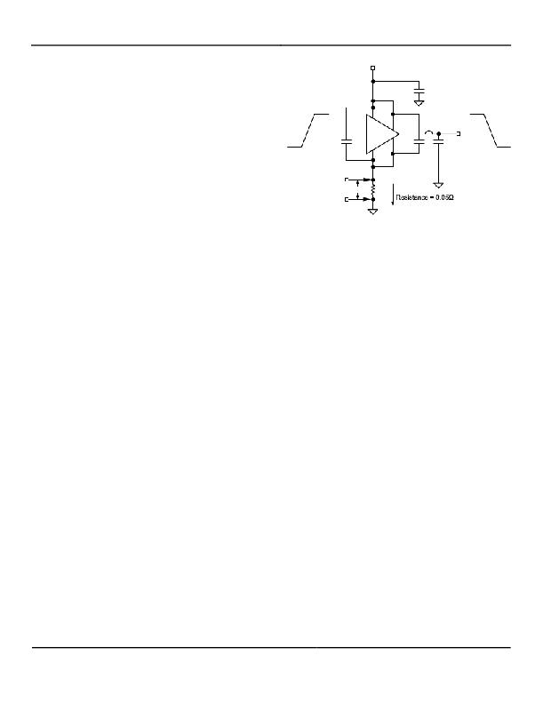
�Figure� 7.� Switching� Time� Due� to� Negative� Feedback�
�The� supply� current� vs.� frequency� and� supply� current� vs.�
�capacitive� load� characteristic� curves� aid� in� determining�
�power� dissipation� calculations.� Table� 1� lists� the�
�maximum� safe� operating� frequency� for� several� power�
�supply� voltages� when� driving� a� 10,000pF� load.� More�
�accurate� power� dissipation� figures� can� be� obtained� by�
�summing� the� three� dissipation� sources.�
�Given� the� power� dissipation� in� the� device,� and� the�
�thermal� resistance� of� the� package,� junction� operating�
�temperature� for� any� ambient� is� easy� to� calculate.� For�
�example,� the� thermal� resistance� of� the� 8-pin� plastic� DIP�
�package,� from� the� data� sheet,� is� 84.6°C/W.� In� a� 25°C�
�ambient,� then,� using� a� maximum� junction� temperature� of�
�150°C,� this� package� will� dissipate� 1478mW.�
�Accurate� power� dissipation� numbers� can� be� obtained� by�
�summing� the� three� sources� of� power� dissipation� in� the�
�device:�
�?� Load� Power� Dissipation� (PL)�
�?� Quiescent� power� dissipation� (PQ)�
�?� Transition� power� dissipation� (PT)�
�Calculation� of� load� power� dissipation� differs� depending�
�on� whether� the� load� is� capacitive,� resistive� or� inductive.�
�Resistive� Load� Power� Dissipation�
�Dissipation� caused� by� a� resistive� load� can� be� calculated�
�as:�
�P� L� =� I� 2� R� O� D�
�where:�
�I� =� the� current� drawn� by� the� load�
�R� O� =� the� output� resistance� of� the� driver� when�
�the� output� is� high,� at� the� power� supply�
�voltage� used.� (See� data� sheet)�
�D� =� fraction� of� time� the� load� is� conducting�
�(duty� cycle).�
�June� 2007�
�9�
�M9999-062707�
�相关PDF资料 |
PDF描述 |
|---|---|
| A7SSG-3710G | DSUB CABL-AFM37G/ AE37G / AFM37G |
| MLV9-C-35 | MICRODRIVER 9X1W DIMMABLE 350MA |
| 395-060-540-802 | CARD EDGE 60POS DL .100X.200 BLK |
| R1D12-2409/H | CONV DC/DC 1W 24VIN +/-09VOUT |
| T95B156M016ESAL | CAP TANT 15UF 16V 20% 1611 |
相关代理商/技术参数 |
参数描述 |
|---|---|
| MIC4421ABN | 功能描述:IC DRIVER MOSFET 9A LS 8-DIP RoHS:否 类别:集成电路 (IC) >> PMIC - MOSFET,电桥驱动器 - 外部开关 系列:- 标准包装:50 系列:- 配置:高端 输入类型:非反相 延迟时间:200ns 电流 - 峰:250mA 配置数:1 输出数:1 高端电压 - 最大(自引导启动):600V 电源电压:12 V ~ 20 V 工作温度:-40°C ~ 125°C 安装类型:通孔 封装/外壳:8-DIP(0.300",7.62mm) 供应商设备封装:8-DIP 包装:管件 其它名称:*IR2127 |
| MIC4421ACM | 功能描述:IC DRIVER MOSFET 9A LS 8-SOIC RoHS:否 类别:集成电路 (IC) >> PMIC - MOSFET,电桥驱动器 - 外部开关 系列:- 标准包装:50 系列:- 配置:高端 输入类型:非反相 延迟时间:200ns 电流 - 峰:250mA 配置数:1 输出数:1 高端电压 - 最大(自引导启动):600V 电源电压:12 V ~ 20 V 工作温度:-40°C ~ 125°C 安装类型:通孔 封装/外壳:8-DIP(0.300",7.62mm) 供应商设备封装:8-DIP 包装:管件 其它名称:*IR2127 |
| MIC4421ACM TR | 功能描述:IC DRIVER MOSFET 9A LS 8-SOIC RoHS:否 类别:集成电路 (IC) >> PMIC - MOSFET,电桥驱动器 - 外部开关 系列:- 标准包装:50 系列:- 配置:高端 输入类型:非反相 延迟时间:200ns 电流 - 峰:250mA 配置数:1 输出数:1 高端电压 - 最大(自引导启动):600V 电源电压:12 V ~ 20 V 工作温度:-40°C ~ 125°C 安装类型:通孔 封装/外壳:8-DIP(0.300",7.62mm) 供应商设备封装:8-DIP 包装:管件 其它名称:*IR2127 |
| MIC4421ACN | 功能描述:IC DRIVER MOSFET 9A LS 8-DIP RoHS:否 类别:集成电路 (IC) >> PMIC - MOSFET,电桥驱动器 - 外部开关 系列:- 标准包装:50 系列:- 配置:高端 输入类型:非反相 延迟时间:200ns 电流 - 峰:250mA 配置数:1 输出数:1 高端电压 - 最大(自引导启动):600V 电源电压:12 V ~ 20 V 工作温度:-40°C ~ 125°C 安装类型:通孔 封装/外壳:8-DIP(0.300",7.62mm) 供应商设备封装:8-DIP 包装:管件 其它名称:*IR2127 |
| MIC4421ACT | 功能描述:IC DRIVER MOSFET 9A LS TO-220-5 RoHS:否 类别:集成电路 (IC) >> PMIC - MOSFET,电桥驱动器 - 外部开关 系列:- 标准包装:50 系列:- 配置:高端 输入类型:非反相 延迟时间:200ns 电流 - 峰:250mA 配置数:1 输出数:1 高端电压 - 最大(自引导启动):600V 电源电压:12 V ~ 20 V 工作温度:-40°C ~ 125°C 安装类型:通孔 封装/外壳:8-DIP(0.300",7.62mm) 供应商设备封装:8-DIP 包装:管件 其它名称:*IR2127 |
发布紧急采购,3分钟左右您将得到回复。