- 您现在的位置:买卖IC网 > Datasheet目录343 > MIC5011YN (Micrel Inc)IC DRIVER MOSF HI/LOW SIDE 8-DIP Datasheet资料下载
参数资料
| 型号: | MIC5011YN |
| 厂商: | Micrel Inc |
| 文件页数: | 11/12页 |
| 文件大小: | 0K |
| 描述: | IC DRIVER MOSF HI/LOW SIDE 8-DIP |
| 标准包装: | 50 |
| 配置: | 高端或低端 |
| 输入类型: | 非反相 |
| 延迟时间: | 25µs |
| 配置数: | 1 |
| 输出数: | 1 |
| 电源电压: | 4.75 V ~ 32 V |
| 工作温度: | -40°C ~ 85°C |
| 安装类型: | 通孔 |
| 封装/外壳: | 8-DIP(0.300",7.62mm) |
| 供应商设备封装: | 8-PDIP |
| 包装: | 管件 |
| 产品目录页面: | 1110 (CN2011-ZH PDF) |
| 其它名称: | 576-2351 MIC5011YN-ND |
�� �
�
�V�
�MIC5011�
�Applications� Information� (Continued)�
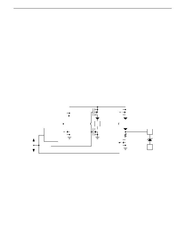
�Gate� Control� Circuit�
�When� applying� the� MIC5011,� it� is� helpful� to� understand� the�
�operation� of� the� gate� control� circuitry� (see� Figure� 12).� The�
�gate� circuitry� can� be� divided� into� two� sections:� 1)� charge�
�pump� (oscillator,� Q1-Q5,� and� the� capacitors)� and� 2)� gate�
�turn-off� switch� (Q6).�
�When� the� MIC5011� is� in� the� OFF� state,� the� oscillator� is�
�turned� off,� thereby� disabling� the� charge� pump.� Q5� is� also�
�turned� off,� and� Q6� is� turned� on.� Q6� holds� the� gate� pin� (G)�
�at� ground� potential� which� effectively� turns� the� external�
�MOSFET� off.�
�Q6� is� turned� off� when� the� MIC5011� is� commanded� on,� and�
�Q5� pulls� the� gate� up� to� supply� (through� 2� diodes).� Next,�
�the� charge� pump� begins� supplying� current� to� the� gate.� The�
�gate� accepts� charge� until� the� gate-source� voltage� reaches�
�12.5V� and� is� clamped� by� the� zener� diode.�
�A� 2-output,� three-phase� clock� switches� Q1-Q4,� providing� a�
�quasi-tripling� action.� During� the� initial� phase� Q4� and� Q2� are�
�Micrel,� Inc.�
�ON.� C1� is� discharged,� and� C2� is� charged� to� supply� through�
�Q5.� For� the� second� phase� Q4� turns� off� and� Q3� turns� on,�
�pushing� pin� C2� above� supply� (charge� is� dumped� into� the�
�gate).� Q3� also� charges� C1.� On� the� third� phase� Q2� turns�
�off� and� Q1� turns� on,� pushing� the� common� point� of� the� two�
�capacitors� above� supply.� Some� of� the� charge� in� C1� makes�
�its� way� to� the� gate.� The� sequence� is� repeated� by� turning�
�Q2� and� Q4� back� on,� and� Q1� and� Q3� off.�
�In� a� low-side� application� operating� on� a� 12� to� 15V� supply,�
�the� MOSFET� is� fully� enhanced� by� the� action� of� Q5� alone.�
�On� supplies� of� more� than� approximately� 14V,� current� ?ows�
�directly� from� Q5� through� the� zener� diode� to� ground.� To�
�prevent� excessive� current� ?ow,� the� MIC5011� supply� should�
�be� limited� to� 15V� in� low-side� applications.�
�The� action� of� Q5� makes� the� MIC5011� operate� quickly� in�
�low-side� applications.� In� high-side� applications� Q5� pre-�
�charges� the� MOSFET� gate� to� supply,� leaving� the� charge�
�pump� to� carry� the� gate� up� to� full� enhancement� 10V� above�
�supply.� Bootstrapped� high-side� drivers� are� as� fast� as� low-�
�side� drivers� since� the� chip� supply� is� boosted� well� above�
�the� drain� at� turn-on.�
�+�
�Q1�
�125pF�
�Q3�
�125pF�
�Q5�
�C1�
�C1�
�COM�
�C2�
�C2�
�OFF�
�100� kHz�
�OSCILLATOR�
�Q2�
�Q4�
�500� ?�
�Q6�
�G� AT� E� CLAMP�
�ZENER�
�G�
�12.5V�
�ON�
�Figure� 12.� Gate� Control�
�Circuit� Detail�
�S�
�July� 2005�
�11�
�MIC5011�
�相关PDF资料 |
PDF描述 |
|---|---|
| MIC5013YN | IC DRIVER MOSFET HI/LO SIDE 8DIP |
| MIC5014YN | IC DRIVER MOSFET HI/LO SIDE 8DIP |
| MIC5016BWM | IC DRIVER MOSF DUAL HI/LO 16SOIC |
| MIC5018YM4 TR | IC DRIVER MOSFET HI SIDE SOT143 |
| MIC5020YM | IC DRIVER MOSF LO SIDE HS 8-SOIC |
相关代理商/技术参数 |
参数描述 |
|---|---|
| MIC5012 | 制造商:MICREL 制造商全称:Micrel Semiconductor 功能描述:Dual High- or Low-Side MOSFET Driver Not Recommended for New Designs |
| MIC5012BN | 制造商:MICREL 制造商全称:Micrel Semiconductor 功能描述:Dual High- or Low-Side MOSFET Driver Not Recommended for New Designs |
| MIC5012BWM | 制造商:MICREL 制造商全称:Micrel Semiconductor 功能描述:Dual High- or Low-Side MOSFET Driver Not Recommended for New Designs |
| MIC5013 | 制造商:MICREL 制造商全称:Micrel Semiconductor 功能描述:Protected High- or Low-Side MOSFET Driver |
| MIC5013_05 | 制造商:MICREL 制造商全称:Micrel Semiconductor 功能描述:Protected High- or Low-Side MOSFET Driver |
发布紧急采购,3分钟左右您将得到回复。