- 您现在的位置:买卖IC网 > Datasheet目录343 > MIC5016BWM (Micrel Inc)IC DRIVER MOSF DUAL HI/LO 16SOIC Datasheet资料下载
参数资料
| 型号: | MIC5016BWM |
| 厂商: | Micrel Inc |
| 文件页数: | 9/12页 |
| 文件大小: | 0K |
| 描述: | IC DRIVER MOSF DUAL HI/LO 16SOIC |
| 标准包装: | 47 |
| 配置: | 高端和低端,独立 |
| 输入类型: | 非反相 |
| 延迟时间: | 2.5ms |
| 配置数: | 1 |
| 输出数: | 2 |
| 电源电压: | 2.75 V ~ 30 V |
| 工作温度: | -40°C ~ 85°C |
| 安装类型: | 表面贴装 |
| 封装/外壳: | 16-SOIC(0.295",7.50mm 宽) |
| 供应商设备封装: | 16-SOIC |
| 包装: | 管件 |
�� �
�
�MIC5016/5017�
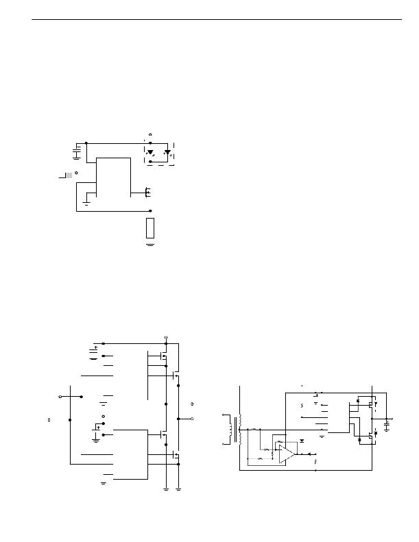
�High� Side� Driver� With� Load� Protection� (Figure� 12)� Al-�
�though� the� MIC5016/17� devices� are� reverse� battery� pro-�
�tected,� the� load� and� power� FET� are� not� in� a� typical� high� side�
�configuration.� In� the� event� of� a� reverse� battery� condition,� the�
�internal� body� diode� of� the� power� FET� will� be� forward� biased.�
�This� allows� the� reversed� supply� to� drive� the� load.�
�Micrel�
�This� scheme� works� with� no� additional� components� as� the�
�relative� time� difference� between� the� rise� and� fall� times� of� the�
�MIC5014� is� large.� However,� this� does� mean� that� there� is�
�considerable� deadtime� (time� when� neither� driver� is� turned�
�on).� If� this� circuit� is� used� to� drive� an� inductive� load,� catch�
�diodes� must� be� used� on� each� half� to� provide� an� alternate� path�
�for� the� kickback� current� that� will� flow� during� this� deadtime.�
�An� MBR2035CT� dual� Schottky� diode� was� used� to� eliminate�
�this� problem.� This� particular� diode� can� handle� 20A� continu-�
�ous� current� and� 150A� peak� current;� therefore� it� should� survive�
�the� rigors� of� an� automotive� environment.� The� diodes� are�
�paralleled� to� reduce� the� switch� loss� (forward� voltage� drop).�
�12V�
�This� circuit� is� also� a� simple� H-bridge� which� can� be� driven� with�
�a� PWM� signal� on� the� input� for� SMPS� or� motor� drive� applica-�
�tions� in� which� high� switching� frequencies� are� not� desired.�
�Synchronous� Rectifier� (Figure� 14)� In� applications� where�
�efficiency� in� terms� of� low� forward� voltage� drops� and� low� diode�
�10μF�
�1/2� MIC5016�
�V+�
�NC�
�MBR2035CT�
�reverse-recovery� losses� is� critical,� power� FETs� are� used� to�
�achieve� rectification� instead� of� a� conventional� diode� bridge.�
�Here,� the� power� FETs� are� used� in� the� third� quadrant� of� the� IV�
�Control� Input�
�ON�
�OFF�
�Input�
�Source�
�Gnd�
�NC�
�NC�
�Gate�
�IRF540�
�characteristic� curve� (FETs� are� installed� essentially� “� back-�
�wards� ”� ).� The� two� FETs� are� connected� such� that� the� top� FET�
�turns� on� with� the� positive� going� AC� cycle,� and� turns� off� when�
�it� swings� negative.� The� bottom� FET� operates� opposite� to� the�
�top� FET.�
�In� the� first� quadrant� of� operation,� the� limitation� of� the� device�
�is� determined� by� breakdown� voltage.� Here,� we� are� limited� by�
�the� turn-on� of� a� parasitic� p-n� body� drain� diode.� If� it� is� allowed�
�to� conduct,� its� reverse� recovery� time� will� crowbar� the� other�
�Figure� 12:� High� Side� Driver� WIth� Load� Protection�
�Push-Pull� Driver� With� No� Cross-Conduction� (Figure� 13)�
�As� the� turn-off� time� of� the� MIC5016/17� devices� is� much� faster�
�than� the� turn-on� time,� a� simple� dual� push-pull� driver� with� no�
�cross� conduction� can� be� made� using� one� MIC5016� and� one�
�MIC5017.� The� same� control� signal� is� applied� to� both� inputs;�
�the� MIC5016� turns� on� with� the� positive� signal,� and� the�
�MIC5017� turns� on� when� it� swings� low.�
�12V�
�power� FET� and� possibly� destroy� it.� The� way� to� prevent� this�
�is� to� keep� the� IR� drop� across� the� device� below� the� cut-in�
�voltage� of� this� diode;� this� is� accomplished� here� by� using� a� fast�
�comparator� to� sense� this� voltage� and� feed� the� appropriate�
�signal� to� the� control� inputs� of� the� MIC5016� device.� Obviously,�
�it� is� very� important� to� use� a� comparator� with� a� fast� slew� rate�
�such� as� the� LM393,� and� fast� recovery� diodes.� 3mV� of� positive�
�feedback� is� used� on� the� comparator� to� prevent� oscillations.�
�At� 3A,� with� an� R� DS� (ON)� of� 0.077� ?� ,� our� forward� voltage� drop�
�per� FET� is� ~� 0.2� V� as� opposed� to� the� 0.7� to� 0.8� V� drop� that� a�
�normal� diode� would� have.� Even� greater� savings� can� be� had�
�MIC5016�
�10μF�
�12�
�10�
�IRFZ40�
�V+� A� Gate� A� 4�
�2�
�V+� B� Source� A�
�by� using� FETs� with� lower� R� DS� (ON)s,� but� care� must� be� taken�
�that� the� peak� currents� and� voltages� do� not� exceed� the� SOA�
�of� the� chosen� FET.�
�14�
�In� A�
�Gate� B�
�6�
�IRFZ40�
�11�
�In� B� Source� B�
�5�
�Control� Input� 1�
�3�
�Gnd�
�V� OUT� A�
�1k� ?�
�10μF�
�12�
�MIC5016�
�V+� A� Gate� A�
�1N914�
�4�
�1RF540�
�*�
�MIC5017�
�Gate� A� 4�
�Gate� B�
�Control� Input� 2�
�12V�
�12�
�V+� A�
�10� 2�
�V+� B� Source� A�
�14� 6�
�In� A� Gate� B�
�IRFZ40�
�V� OUT� B�
�IRFZ40�
�110V� AC�
�Caltronics�
�T126C3�
�25.2V�
�V� CT�
�30m� ?�
�10� ?�
�10k� ?�
�56k� ?�
�1N914� (2)�
�10� 2�
�V+� B� Source� A�
�14� 6�
�In� A�
�11� 5�
�In� B� Source� B�
�3� Gnd�
�1N914�
�1RF540�
�4700μF�
�*�
�V� OUT� =�
�18V,� 3A�
�11�
�In� B� Source� B�
�5�
�10k� ?�
�1/2� LM393�
�1k� ?�
�*� Parasitic� body� diode�
�3�
�Gnd�
�Figure� 14:� High� Efficiency� 60� Hz�
�Figure� 13:� Push-Pull� Driver�
�Synchronous� Rectifier�
�October� 1998�
�9�
�MIC5016/5017�
�相关PDF资料 |
PDF描述 |
|---|---|
| MIC5018YM4 TR | IC DRIVER MOSFET HI SIDE SOT143 |
| MIC5020YM | IC DRIVER MOSF LO SIDE HS 8-SOIC |
| MIC5021YN | IC DRIVER MOSFET HI SIDE HS 8DIP |
| MIC5400BWM | IC LED DRIVER RGB 28-SOIC |
| MKP1V240RL | SIDAC BIDIR 0.9A 240V DO-41 |
相关代理商/技术参数 |
参数描述 |
|---|---|
| MIC5016BWM TR | 制造商:Micrel Inc 功能描述:MOSFET DRVR 2-OUT Hi/Lo Side Non-Inv 16-Pin SOIC W T/R |
| MIC5016YN | 功能描述:IC DRIVER MOSF DUAL HI/LOW 14DIP RoHS:是 类别:集成电路 (IC) >> PMIC - MOSFET,电桥驱动器 - 外部开关 系列:- 标准包装:50 系列:- 配置:高端 输入类型:非反相 延迟时间:200ns 电流 - 峰:250mA 配置数:1 输出数:1 高端电压 - 最大(自引导启动):600V 电源电压:12 V ~ 20 V 工作温度:-40°C ~ 125°C 安装类型:通孔 封装/外壳:8-DIP(0.300",7.62mm) 供应商设备封装:8-DIP 包装:管件 其它名称:*IR2127 |
| MIC5016YWM | 功能描述:IC DRIVER MOSF DUAL HI/LO 16SOIC RoHS:是 类别:集成电路 (IC) >> PMIC - MOSFET,电桥驱动器 - 外部开关 系列:- 标准包装:50 系列:- 配置:高端 输入类型:非反相 延迟时间:200ns 电流 - 峰:250mA 配置数:1 输出数:1 高端电压 - 最大(自引导启动):600V 电源电压:12 V ~ 20 V 工作温度:-40°C ~ 125°C 安装类型:通孔 封装/外壳:8-DIP(0.300",7.62mm) 供应商设备封装:8-DIP 包装:管件 其它名称:*IR2127 |
| MIC5017BN | 制造商:MICREL 制造商全称:Micrel Semiconductor 功能描述:Low-Cost Dual High- or Low-Side MOSFET Driver |
| MIC5017BWM | 制造商:Micrel Inc 功能描述:MOSFET DRVR 2-OUT Hi/Lo Side Inv 16-Pin SOIC W 制造商:Rochester Electronics LLC 功能描述:- Bulk |
发布紧急采购,3分钟左右您将得到回复。