参数资料
| 型号: | MIC5311-NLYML TR |
| 厂商: | Micrel Inc |
| 文件页数: | 9/11页 |
| 文件大小: | 0K |
| 描述: | IC REG LDO 2.85V/2.7V .3A 10-MLF |
| 标准包装: | 1 |
| 稳压器拓扑结构: | 正,固定式 |
| 输出电压: | 2.85V,2.7V |
| 输入电压: | 2.5 V ~ 5.5 V |
| 电压 - 压降(标准): | 0.12V @ 300mA |
| 稳压器数量: | 2 |
| 电流 - 输出: | 300mA |
| 电流 - 限制(最小): | 350mA |
| 工作温度: | -40°C ~ 125°C |
| 安装类型: | 表面贴装 |
| 封装/外壳: | 10-VFDFN 裸露焊盘,10-MLF? |
| 供应商设备封装: | 10-MLF?(3x3) |
| 包装: | 标准包装 |
| 产品目录页面: | 1102 (CN2011-ZH PDF) |
| 其它名称: | 576-1902-6 |
�� �
�
�Micrel,� Inc.�
�Functional� Description�
�The� MIC5311� is� a� high� performance,� low� quiescent�
�current� power� management� IC� consisting� of� two� μCap�
�low� dropout� regulators� with� a� LowQ?� mode� featuring�
�lower� operating� current.� Both� regulators� are� capable� of�
�sourcing� 300mA.�
�Enable� 1� and� 2�
�The� enable� inputs� allow� for� logic� control� of� both� output�
�voltages� with� individual� enable� inputs.� The� enable� input�
�is� active� high,� requiring� 1.0V� for� guaranteed� operation.�
�The� enable� input� is� CMOS� logic� and� cannot� be� left�
�floating.�
�LowQ� ?� Mode�
�The� LowQ?� pin� is� logic� level� low,� requiring� <0.2V� to�
�enter� the� LowQ?� mode.� The� LowQ?� pin� cannot� be� left�
�MIC5311�
�Thermal� Considerations�
�The� MIC5311� is� designed� to� provide� 300mA� of�
�continuous� current� per� channel� in� a� very� small� MLF�
�package.� Maximum� power� dissipation� can� be� calculated�
�based� on� the� output� current� and� the� voltage� drop� across�
�the� part.� To� determine� the� maximum� power� dissipation�
�of� the� package,� use� the� junction-to-ambient� thermal�
�resistance� of� the� device� and� the� following� basic�
�equation:�
�P� D� (max)� =� (T� J� (max)� -� T� A� )� /� θ� JA�
�T� J� (max)� is� the� maximum� junction� temperature� of� the�
�die,� 125°C,� and� T� A� is� the� ambient� operating�
�temperature.� θ� JA� is� layout� dependent;� Table� 1� shows�
�examples� of� the� junction-to-ambient� thermal� resistance�
�for� the� MIC5311.�
�floating.� Features� of� the� LowQ?� mode� include� lower�
�total� quiescent� current� of� typically� 7uA.�
�Input� Capacitor�
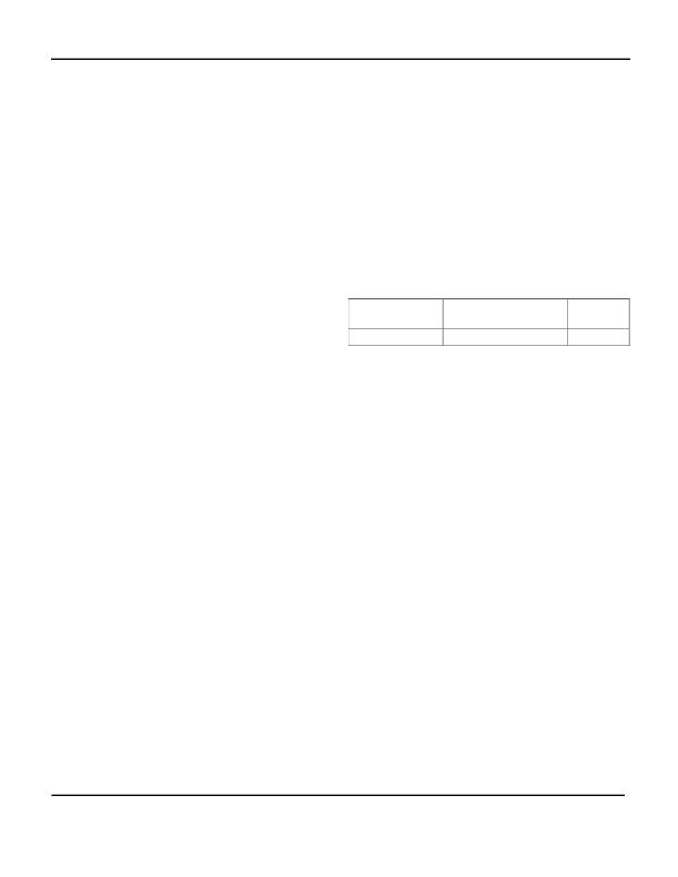
�Package�
�3x3� MLF?-10�
�θ� JA� Recommended�
�Minimum� Footprint�
�63°C/W�
�θ� JC�
�2°C/W�
�Good� bypassing� is� recommended� from� input� to� ground�
�to� help� improve� AC� performance.� A� 1μF� capacitor� or�
�greater� located� close� to� the� IC� is� recommended.� Larger�
�load� currents� may� require� larger� capacitor� values.�
�Bypass� Capacitor�
�The� internal� reference� voltage� of� the� MIC5311� can� be�
�bypassed� with� a� capacitor� to� ground� to� reduce� output�
�noise� and� increase� input� ripple� rejection� (PSRR).� A�
�quick-start� feature� allows� for� quick� turn-on� of� the� output�
�voltage.� The� recommended� nominal� bypass� capacitor� is�
�0.01μF,� but� an� increase� will� result� in� longer� turn� on�
�times� t� on� .�
�Output� Capacitor�
�Each� regulator� output� requires� a� 2.2μF� ceramic� output�
�capacitor� for� stability.� The� output� capacitor� value� can� be�
�increased� to� improve� transient� response,� but�
�performance� has� been� optimized� for� a� 2.2μF� ceramic�
�type� output� capacitor.� X7R/X5R� dielectric-type� ceramic�
�capacitors� are� recommended� because� of� their�
�temperature� performance.� X7R-type� capacitors� change�
�capacitance� by� 15%� over� their� operating� temperature�
�range� and� are� the� most� stable� type� of� ceramic�
�capacitors.� Z5U� and� Y5V� dielectric� capacitors� change�
�value� by� as� much� as� 50%� to� 60%� respectively� over� their�
�operating� temperature� ranges.� To� use� a� ceramic� chip�
�capacitor� with� Y5V� dielectric,� the� value� must� be� much�
�higher� than� a� X7R� ceramic� capacitor� to� ensure� the� same�
�minimum� capacitance� over� the� equivalent� operating�
�temperature� range.�
�Table� 1.� MLF?� Thermal� Resistance�
�The� actual� power� dissipation� of� the� regulator� circuit� can�
�be� determined� using� the� equation:�
�P� DTOTAL� =� P� D� LDO1� +� P� D� LDO2�
�P� D� LDO1� =� (V� IN� -V� OUT1� )� x� I� OUT1�
�P� D� LDO2� =� (V� IN� -V� OUT2� )� x� I� OUT2�
�Substituting� P� D(max)� for� P� D� and� solving� for� the� operating�
�conditions� that� are� critical� to� the� application� will� give� the�
�maximum� operating� conditions� for� the� regulator� circuit.�
�For� example,� when� operating� the� MIC5311� at� 60°C� with�
�a� minimum� footprint� layout,� the� maximum� load� currents�
�can� be� calculated� as� follows:�
�P� D� (max)� =� (T� J� (max)� -� T� A� )� /� θ� JA�
�P� D� (max)� =� (125°C� -� 60°C)� /� 63°C/W�
�P� D� (max)� =� 1.03W�
�The� junction-to-ambient� thermal� resistance� for� the�
�minimum� footprint� is� 63°C/W� ,� from� Table� 1.� The�
�maximum� power� dissipation� must� not� be� exceeded� for�
�proper� operation.� Using� a� lithium-ion� battery� as� the�
�supply� voltage� of� 4.2V,� 1.8V� OUT� /150mA� for� channel� 1�
�and� 2.8V� OUT� /100mA� for� channel� 2,� power� dissipation�
�can� be� calculated� as� follows:�
�P� D� LDO1� =� (V� IN� -V� OUT1� )� x� I� OUT1�
�P� D� LDO1� =� (4.2V-1.8V)� x� 150mA�
�P� D� LDO1� =� 360mW�
�P� D� LDO2� =� (V� IN� -V� OUT2� )� x� I� OUT2�
�P� D� LDO1� =� (4.2V-2.8V)� x� 100mA�
�P� D� LDO1� =� 140mW�
�March� 2006�
�9�
�M9999-032706�
�(408)� 955-1690�
�相关PDF资料 |
PDF描述 |
|---|---|
| MIC5313-F5YMT TR | IC REG LDO 1.5V/1.3V .3A 10-TMLF |
| MIC5314-F4YMT TR | IC REG LDO 1.5V/1.2V .3A 12-TMLF |
| MIC5315-F5CYMT TR | IC REG LDO 1.5V/1.3V/1V 10-TMLF |
| MIC5316-F4CYMT TR | IC REG LDO 1.5V/1.2V/1V 12-TMLF |
| MIC5318YMT TR | IC REG LDO ADJ .3A 6-TMLF |
相关代理商/技术参数 |
参数描述 |
|---|---|
| MIC5311-NNYML TR | 功能描述:低压差稳压器 - LDO Portable Power IC in 3mm x 3mm MLF LowQ Dual Cap LDO (Lead Free) RoHS:否 制造商:Texas Instruments 最大输入电压:36 V 输出电压:1.4 V to 20.5 V 回动电压(最大值):307 mV 输出电流:1 A 负载调节:0.3 % 输出端数量: 输出类型:Fixed 最大工作温度:+ 125 C 安装风格:SMD/SMT 封装 / 箱体:VQFN-20 |
| MIC5312-DKBML TR | 功能描述:IC REG LDO 1.85V/2.6V .3A 10-MLF RoHS:否 类别:集成电路 (IC) >> PMIC - 稳压器 - 线性 系列:- 标准包装:500 系列:- 稳压器拓扑结构:正,固定式 输出电压:12V 输入电压:14.5 V ~ 35 V 电压 - 压降(标准):- 稳压器数量:1 电流 - 输出:500mA 电流 - 限制(最小):- 工作温度:-40°C ~ 125°C 安装类型:通孔 封装/外壳:TO-205AD,TO-39-3 金属罐 供应商设备封装:TO-39 包装:散装 其它名称:*LM78M12CH*LM78M12CH/NOPBLM78M12CH |
| MIC5312-DKYML TR | 功能描述:低压差稳压器 - LDO Portable Power IC in 3mm x 3mm MLF LowQ Dual Cap LDO w/Integrated POR RoHS:否 制造商:Texas Instruments 最大输入电压:36 V 输出电压:1.4 V to 20.5 V 回动电压(最大值):307 mV 输出电流:1 A 负载调节:0.3 % 输出端数量: 输出类型:Fixed 最大工作温度:+ 125 C 安装风格:SMD/SMT 封装 / 箱体:VQFN-20 |
| MIC5312-GMBML TR | 功能描述:IC REG LDO 1.8V/2.8V .3A 10-MLF RoHS:否 类别:集成电路 (IC) >> PMIC - 稳压器 - 线性 系列:- 标准包装:500 系列:- 稳压器拓扑结构:正,固定式 输出电压:12V 输入电压:14.5 V ~ 35 V 电压 - 压降(标准):- 稳压器数量:1 电流 - 输出:500mA 电流 - 限制(最小):- 工作温度:-40°C ~ 125°C 安装类型:通孔 封装/外壳:TO-205AD,TO-39-3 金属罐 供应商设备封装:TO-39 包装:散装 其它名称:*LM78M12CH*LM78M12CH/NOPBLM78M12CH |
| MIC5312-GMYML TR | 功能描述:低压差稳压器 - LDO Portable Power IC in 3mm x 3mm MLF LowQ Dual Cap LDO w/Integrated POR RoHS:否 制造商:Texas Instruments 最大输入电压:36 V 输出电压:1.4 V to 20.5 V 回动电压(最大值):307 mV 输出电流:1 A 负载调节:0.3 % 输出端数量: 输出类型:Fixed 最大工作温度:+ 125 C 安装风格:SMD/SMT 封装 / 箱体:VQFN-20 |
发布紧急采购,3分钟左右您将得到回复。