参数资料
| 型号: | MICRF302YML TR |
| 厂商: | Micrel Inc |
| 文件页数: | 13/15页 |
| 文件大小: | 0K |
| 描述: | IC ENCODER PAR QWIKRADIO 10-MLF |
| 标准包装: | 1 |
| 类型: | 编码器 |
| 应用: | RF,IR |
| 安装类型: | 表面贴装 |
| 封装/外壳: | 10-VFDFN 裸露焊盘,10-MLF? |
| 供应商设备封装: | 10-MLF?(3x3) |
| 包装: | 标准包装 |
| 产品目录页面: | 571 (CN2011-ZH PDF) |
| 其它名称: | 576-3337-6 |
Micrel, Inc.
MICRF302
March 2010
7
M9999-032610-A
MICRF302
ENCODER
DOUT
DO
D0
D1
D2
D3
TRANSMITTER
RECEIVER
MCU
TXEN
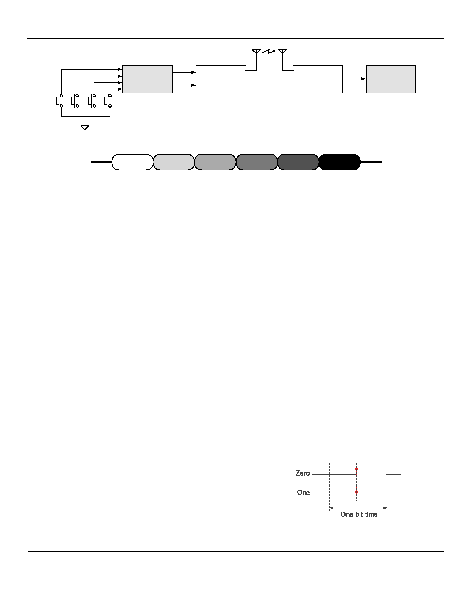
Figure 4. Parallel Encoder / Decoder Configuration
PREAMBLE
DEAD TIME
SYNC
ADDRESS
DATA
CRC
Figure 5. Data Transmission Packet Format
Operation Overview
The Figure 4 shows the basic operation of a parallel
encoder/decoder configuration. When a button is pushed
(known as a push event), the MICRF302 Encoder sends
packets of data to the transmitter. Each packet contains
encoded data bits, suitable for transmission across an ASK
or FSK RF communications channel. The receiver
demodulates the baseband information from the RF carrier,
which is then decoded by the MCU.
Data Transmission
In any communications link we must be sure that the
decoder puts out what the encoder puts in. Lost data is
acceptable when the encoder and decoder are out of range,
but incorrect data is completely unacceptable when the
encoder and decoder are within range. Micrel’s MICRF302
uses an error management hierarchy to prevent bad data
getting through the link:
1. Data is encoded using RF receiver-friendly
Manchester encoding
2. An industry-standard CRC (Cyclic Redundancy
Check) ensures that data is good before being
accepted by the decoder
3. Data is sent in packets. Each packet has a
preamble, sync field, and a payload. Packets are
sent in groups of four. So even though four identical
packets are transmitted, a single valid packet
received by the Decoder is sufficient to change the
Decoder’s outputs. Please see operating manual of
the MICRF302 for details.
Packet Format
Each data packet consists of a number of fields, shown in
Figure 5. A packet consists of six fields:
1. Preamble (32 bits, all zero) is for receiver and
decoder wakeup and synchronization
2. Dead Time (3 bit-times) allows the receiver’s AGC
to increase its sensitivity
3. Sync (four bits, 1111) identifies the end of the
preamble and the start of the payload
4. DEVADR—20 bits of Device Address—identifies
one unique Encoder that’s transmitting. decoders
compare the DEVADR field against their own value
and only accept the packet if a match is found. The
20-bit device address is programmed at the factory
to a unique value for each part.
5. Data (8 bits) carries the “real” information within the
packet.
6. CRC—Cyclic Redundancy Check—(8 bits) lets the
Decoder check for errors in the packet
Data Format
Manchester-coded data has two distinguishing features that
make it an excellent choice for low-cost RF data exchange:
1. Its 50% duty cycle is very friendly to RF receivers.
2. It always has a transition at the center of every bit
(Figure 6). This certainty of a transition simplifies the
decoder’s task of recovering the encoder’s clock
rate and then actually decoding the data stream.
Manchester-coded data is shown here:
Figure 6. Manchester Coded Data
相关PDF资料 |
PDF描述 |
|---|---|
| MK10DN512ZVLL10 | IC ARM CORTEX MCU 512KB 100LQFP |
| MK10DX128VFM5 | IC ARM CORTEX MCU 128KB 32QFN |
| MK20DN512ZVLL10 | IC ARM CORTEX MCU 512KB 100LQFP |
| MK20DN512ZVLQ10 | IC ARM CORTEX MCU 512KB 144LQFP |
| MK20DN512ZVMC10 | IC ARM CORTEX MCU 512KB 121BGA |
相关代理商/技术参数 |
参数描述 |
|---|---|
| MICRF405 | 制造商:MICREL 制造商全称:Micrel Semiconductor 功能描述:290MHz-980MHz ISM Band ASK / FSK Transmitter |
| MICRF405DEV1-315 | 功能描述:射频开发工具 MICRF405 Eval Board for Experimental Use only RoHS:否 制造商:Taiyo Yuden 产品:Wireless Modules 类型:Wireless Audio 工具用于评估:WYSAAVDX7 频率: 工作电源电压:3.4 V to 5.5 V |
| MICRF405DEV1-433 | 功能描述:射频开发工具 MICRF405 Eval Board for Experimental Use only RoHS:否 制造商:Taiyo Yuden 产品:Wireless Modules 类型:Wireless Audio 工具用于评估:WYSAAVDX7 频率: 工作电源电压:3.4 V to 5.5 V |
| MICRF405DEV1-868 | 功能描述:射频开发工具 MICRF405 Eval Board for Experimental Use only RoHS:否 制造商:Taiyo Yuden 产品:Wireless Modules 类型:Wireless Audio 工具用于评估:WYSAAVDX7 频率: 工作电源电压:3.4 V to 5.5 V |
| MICRF405DEV1-915 | 功能描述:射频开发工具 MICRF405 Eval Board for Experimental Use only RoHS:否 制造商:Taiyo Yuden 产品:Wireless Modules 类型:Wireless Audio 工具用于评估:WYSAAVDX7 频率: 工作电源电压:3.4 V to 5.5 V |
发布紧急采购,3分钟左右您将得到回复。