- 您现在的位置:买卖IC网 > PDF目录224285 > MICRF610TR (MICREL INC) 868-870 MHz ISM Band Transceiver Module PDF资料下载
参数资料
| 型号: | MICRF610TR |
| 厂商: | MICREL INC |
| 元件分类: | 通信及网络 |
| 英文描述: | 868-870 MHz ISM Band Transceiver Module |
| 中文描述: | SPECIALTY TELECOM CIRCUIT, QMA16 |
| 封装: | 11.50 X 14.10 MM, MODULE-16 |
| 文件页数: | 6/20页 |
| 文件大小: | 698K |
| 代理商: | MICRF610TR |
Micrel, Inc.
MICRF610/MICRF610Z
July 2006
14
M9999-120205
Transceiver Sync/Non-Synchronous Mode
A6..A0
D7
D6
D5
D4
D3
D2
D1
D0
0000000
LNA_by
PA2
PA1
PA0
Sync_en
Mode1
Mode0
’1’
0000110
-
‘0’
BitSync_clkS2 BitSync_clkS1 BitSync_clkS0 BitRate_clkS2
0000111 BitRate_clkS1 BitRate_clkS0
RefClk_K5
RefClk_K4
RefClk_K3
RefClk_K2
RefClk_K1
RefClk_K0
Sync_en
State
Comments
0
Rx: Bit
synchronization off
Transparent reception of data
0
Tx: DataClk pin off
Transparent transmission of
data
1
Rx: Bit
synchronization on
Bit-clock is generated by
transceiver
1
Tx: DataClk pin on
Bit-clock is generated by
transceiver
When Sync_en = 1, it will enable the bit synchronizer in
receive mode. The bit synchronizer clock needs to be
programmed,
see
chapter
Bit
synchronizer.
The
synchronized clock will be set out on pit DataClk.
In transmit mode, when Sync_en = 1, the clock signal on
pin DataClk is a programmed bit rate clock. Now the
transceiver controls the actual data rate. The data to be
transmitted will be sampled on rising edge of DataClk. The
micro controller can therefore use the negative edge to
change the data to be transmitted. The clock used for this
purpose, BitRate-clock, is programmed in the same way
as the modulator clock and the bit synchronizer clock:
lkS)
-BITRATE_c
(7
XCO
K
BITRATE_CL
2
Refclk_K
f
×
=
where
fBITRATE_CLK: The clock frequency used to control the
bit rate, should be equal to the bit rate (bit rate of 20
kbit/sec requires a clock frequency of 20kHz)
fXCO: Crystal oscillator frequency
Refclk_K: 6 bit divider, values between 1 and 63
BitRate_clkS: Bit rate setting, values between 0 and
6
Data Interface
The MICRF610 interface can be divided in to two separate
interfaces, a “programming interface” and a “Data
interface”. The “programming interface” has a three wire
serial programmable interface and is described in chapter
Programming.
The “data interface” can be programmed to sync-/non-
synchronous mode. In synchronous mode the MICRF610
is defined as “Master” and provides a data clock that
allows users to utilize low cost micro controller reference
frequency.
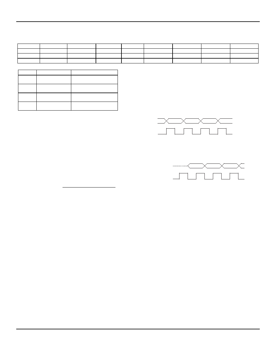
The data interface is defined in such a way that all user
actions should take place on falling edge and is illustrated
Figure 7 and 8. The two figures illustrate the relationship
between DATACLK and DATAIXO in receive mode and
transmit mode.
MICRF610 will present data on rising edge and the
“USER” sample data on falling edge in receive mode.
DATAIXO
DATACLK
Figure 7. Data interface in Receive Mode
The User presents data on falling edge and MICRF610 samples
on rising edge in transmit mode.
DATAIXO
DATACLK
Figure 8. Data interface in Transmit Mode
Receiver
The receiver is a zero intermediate frequency (IF) type in
order to make channel filtering possible with low-power
integrated low-pass filters. The receiver consists of a low
noise amplifier (LNA) that drives a quadrature mixer pair.
The mixer outputs feed two identical signal channels in
phase quadrature. Each channel includes a pre-amplifier,
a third order Sallen-Key RC lowpass filter from strong
adjacent channel signals and finally a limiter. The main
channel filter is a switched-capacitor implementation of a
six-pole elliptic lowpass filter. The elliptic filter minimizes
the total capacitance required for a given selectivity and
dynamic range. The cut-off frequency of the Sallen-Key
RC filter can be programmed to four different frequencies:
100kHz, 150kHz, 230kHz and 340kHz. The demodulator
demodulates the I and Q channel outputs and produces a
digital data output. If detects the relative phase of the I and
Q channel signal. If the I channel signal lags the Q
channel, the FSK tone frequency lies above the LO
frequency (data ‘1’). If the I channel leads the Q channel,
the FSK tone lies below the LO frequency (data ‘0’). The
output of the receiver is available on the DataIXO pin. A
RSSI circuit (receive signal strength indicator) indicates
the received signal level.
相关PDF资料 |
PDF描述 |
|---|---|
| MICRF610 | 868-870 MHz ISM Band Transceiver Module |
| MIK0-55S | 55 CONTACT(S), POLYETHYLENE, FEMALE, CIRCULAR CONNECTOR, CRIMP, RECEPTACLE |
| MIK0-7S | 7 CONTACT(S), POLYETHYLENE, FEMALE, CIRCULAR CONNECTOR, CRIMP, RECEPTACLE |
| MIK6-55P | 55 CONTACT(S), POLYETHYLENE, MALE, CIRCULAR CONNECTOR, CRIMP, PLUG |
| MIK6-7P | 7 CONTACT(S), POLYETHYLENE, MALE, CIRCULAR CONNECTOR, CRIMP, PLUG |
相关代理商/技术参数 |
参数描述 |
|---|---|
| MICRF610Z | 功能描述:IC RF MOD 868-870MHZ 11.5X14.1MM RoHS:是 类别:RF/IF 和 RFID >> RF 收发器 系列:- 产品培训模块:Lead (SnPb) Finish for COTS Obsolescence Mitigation Program 标准包装:30 系列:- 频率:4.9GHz ~ 5.9GHz 数据传输率 - 最大:54Mbps 调制或协议:* 应用:* 功率 - 输出:-3dBm 灵敏度:- 电源电压:2.7 V ~ 3.6 V 电流 - 接收:* 电流 - 传输:* 数据接口:PCB,表面贴装 存储容量:- 天线连接器:PCB,表面贴装 工作温度:-25°C ~ 85°C 封装/外壳:68-TQFN 裸露焊盘 包装:管件 |
| MICRF610Z TR | 功能描述:IC RF MOD 868-870MHZ 11.5X14.1MM RoHS:是 类别:RF/IF 和 RFID >> RF 收发器 系列:- 产品培训模块:Lead (SnPb) Finish for COTS Obsolescence Mitigation Program 标准包装:30 系列:- 频率:4.9GHz ~ 5.9GHz 数据传输率 - 最大:54Mbps 调制或协议:* 应用:* 功率 - 输出:-3dBm 灵敏度:- 电源电压:2.7 V ~ 3.6 V 电流 - 接收:* 电流 - 传输:* 数据接口:PCB,表面贴装 存储容量:- 天线连接器:PCB,表面贴装 工作温度:-25°C ~ 85°C 封装/外壳:68-TQFN 裸露焊盘 包装:管件 |
| MICRF620 | 制造商:MICREL 制造商全称:Micrel Semiconductor 功能描述:434MHz ISM Band Transceiver Module |
| MICRF620_0608 | 制造商:MICREL 制造商全称:Micrel Semiconductor 功能描述:434MHz ISM Band Transceiver Module |
| MICRF620DEV1 | 制造商:Micrel Inc 功能描述:DEVELOPMENT KIT TRANSCEIVER 433MHZ |
发布紧急采购,3分钟左右您将得到回复。