- 您现在的位置:买卖IC网 > PDF目录266554 > MIT-076-02-L-D (SAMTEC INC) 152 CONTACT(S), MALE, STRAIGHT BOARD STACKING CONNECTOR, SURFACE MOUNT PDF资料下载
参数资料
| 型号: | MIT-076-02-L-D |
| 厂商: | SAMTEC INC |
| 元件分类: | 电路板相叠连接器 |
| 英文描述: | 152 CONTACT(S), MALE, STRAIGHT BOARD STACKING CONNECTOR, SURFACE MOUNT |
| 封装: | ROHS COMPLIANT |
| 文件页数: | 1/1页 |
| 文件大小: | 466K |
| 代理商: | MIT-076-02-L-D |
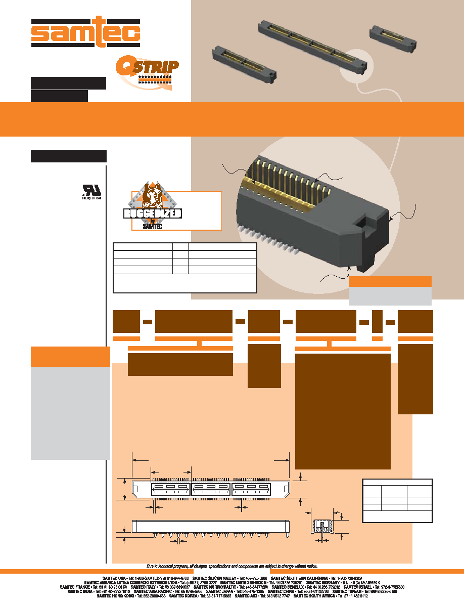
(0,635mm) .025"
MIT SERIES
MIT–076–01–L–D
MIT–019–01–F–D
MIT–038–01–F–D
Choice of
mated heights
Polarized
76 signal lines
per linear inch
Integral metal plane
for power or ground
WWW.SAMTEC.COM
F-211
(12,70)
.500
(No. of Positions/19) x (12,70) .500 + (11,43) .450
(0,20)
.008
(0,635)
.025
(0,58) .023 x (0,38) .015
A
(5,97)
.235
(7,11)
.280
(0,38)
.015
(1,40)
.055
01
02
(7,11)
.280
LEAD
STYLE
A
(4,27) .168
(7,26) .286
–01
–02
MATED
HEIGHT
(5,00) .197
(8,00) .315
Processing conditions will
affect mated height.
STACK HEIGHTS
For complete specications and
recommended PCB layouts see
www.samtec.com?MIT
Insulator Material:
Liquid Crystal
Polymer
Contact Material:
Phosphor Bronze
Plating:
Au or Sn over 50" (1,27m) Ni
Current Rating:
Contacts: 1.6A @ 80°C
Ground Plane: 8.7A @ 80°C
Operating Temp Range:
-55°C to +125°C
Voltage Rating:
275 VAC
Max Cycles:
100
RoHS Compliant:
Yes
Processing:
Lead–Free Solderable:
Yes
SMT Lead Coplanarity:
(0,10mm) .004" max (019-076)
Board Stacking:
For applications requiring
more than two connectors per
board or 76 positions or higher,
contact ipg@samtec.com
11mm, 16mm, 18,75mm
and 22mm stack height
30" (0,76m) Gold
Differential Pair and
“Partitionable” (combine
differential & single-
ended banks in same
connector) available.
95, 114 and 133
positions per row
Edge Mount
Call Samtec.
APPLICATION
SPECIFIC OPTION
Note: Rugged through-hole ground plane soldered to board
(requires paste-over-hole, not press t) for added retention to PCB.
*Note: –C Plating passes
10 year MFG testing
Note: Some lengths, styles
and options are non-standard,
non-returnable.
MIT
NO. OF POSITIONS
PER ROW
D
PLATING
OPTION
–F
= Gold Flash on Signal Pins and
Ground Plane, Matte Tin on tails
–L
= 10" (0,25m) Gold on
Signal Pins and Ground Plane,
Matte Tin on tails
–C*
= Electro-Polished Selective
50" (1,27m) min Au over 150"
(3,81m) Ni on Signal Pins in contact
area, 10" (0,25m) min Au over
50" (1,27m) Ni on Ground Plane
in contact area, Matte Tin over 50"
(1,27m) min Ni on all solder tails
LEAD
STYLE
Specify
LEAD
STYLE
from
chart
–019, –038, –057, –076
(38 total positions per bank)
OTHER
OPTION
–K
= (7,00mm)
.275" DIA
Polyimide
lm Pick &
Place Pad
–TR
= Tape &
Reel
ALSO AVAILABLE
Board Spacing Standoffs.
See SO Series.
SPECIFICATIONS
Board Mates:
MIS
Cable Mates:
MICD
5mm Stack Height
Type
Rated @ 3dB Insertion Loss
Single-Ended Signaling
–D
8.5 GHz / 17 Gbps
Differential Pair Signaling
–D
8.5 GHz / 17 Gbps
Differential Pair Signaling
–DP
9.5 GHz / 19 Gbps
Performance data for other stack heights and complete
test data available at www.samtec.com?MIT or contact
sig@samtec.com
THROUGH-HOLE GROUND PLANE HEADER
Mixed
technology
footprint
相关PDF资料 |
PDF描述 |
|---|---|
| MTMS-101-25-G-D-125 | 2 CONTACT(S), MALE, STRAIGHT BOARD STACKING CONNECTOR, SOLDER |
| MTMS-101-25-G-S-125 | 1 CONTACT(S), MALE, STRAIGHT BOARD STACKING CONNECTOR, SOLDER |
| MTMS-102-25-G-D-125 | 4 CONTACT(S), MALE, STRAIGHT BOARD STACKING CONNECTOR, SOLDER |
| MTMS-103-25-G-D-125 | 6 CONTACT(S), MALE, STRAIGHT BOARD STACKING CONNECTOR, SOLDER |
| MTMS-103-25-G-S-125 | 3 CONTACT(S), MALE, STRAIGHT BOARD STACKING CONNECTOR, SOLDER |
相关代理商/技术参数 |
参数描述 |
|---|---|
| MIT-076-02-L-D-K | 制造商:Samtec Inc 功能描述:CONN MICRO HS TERM STRP HDR 152 POS 0.64MM SLDR ST TH/SMD - Bulk |
| MIT-076-02-L-D-K-TR | 制造商:Samtec Inc 功能描述:CONN MICRO HS TERM STRP HDR 152 POS 0.64MM SLDR ST TH/SMD - Tape and Reel |
| MIT-076-02-L-D-TR | 制造商:Samtec Inc 功能描述:CONN MICRO HS TERM STRP HDR 152 POS 0.64MM SLDR ST TH/SMD - Tape and Reel |
| MIT-076-02-L-D-TY | 制造商:Samtec Inc 功能描述:.635MM DOUBLE ROW HS TERMINAL ASSEMBLY - Bulk |
| MIT-076-03-C-D | 制造商:Samtec Inc 功能描述:.635MM DOUBLE ROW HS TERMINAL ASSEMBLY - Bulk |
发布紧急采购,3分钟左右您将得到回复。