- 您现在的位置:买卖IC网 > PDF目录81683 > MMSZ13ET1G (ON SEMICONDUCTOR) 13 V, 0.5 W, SILICON, UNIDIRECTIONAL VOLTAGE REGULATOR DIODE PDF资料下载
参数资料
| 型号: | MMSZ13ET1G |
| 厂商: | ON SEMICONDUCTOR |
| 元件分类: | 齐纳二极管 |
| 英文描述: | 13 V, 0.5 W, SILICON, UNIDIRECTIONAL VOLTAGE REGULATOR DIODE |
| 封装: | PLASTIC, CASE 425-04, 2 PIN |
| 文件页数: | 1/7页 |
| 文件大小: | 81K |
| 代理商: | MMSZ13ET1G |
Semiconductor Components Industries, LLC, 2006
January, 2006 Rev. 5
1
Publication Order Number:
MMSZ2V4ET1/D
MMSZ2V4ET1 Series
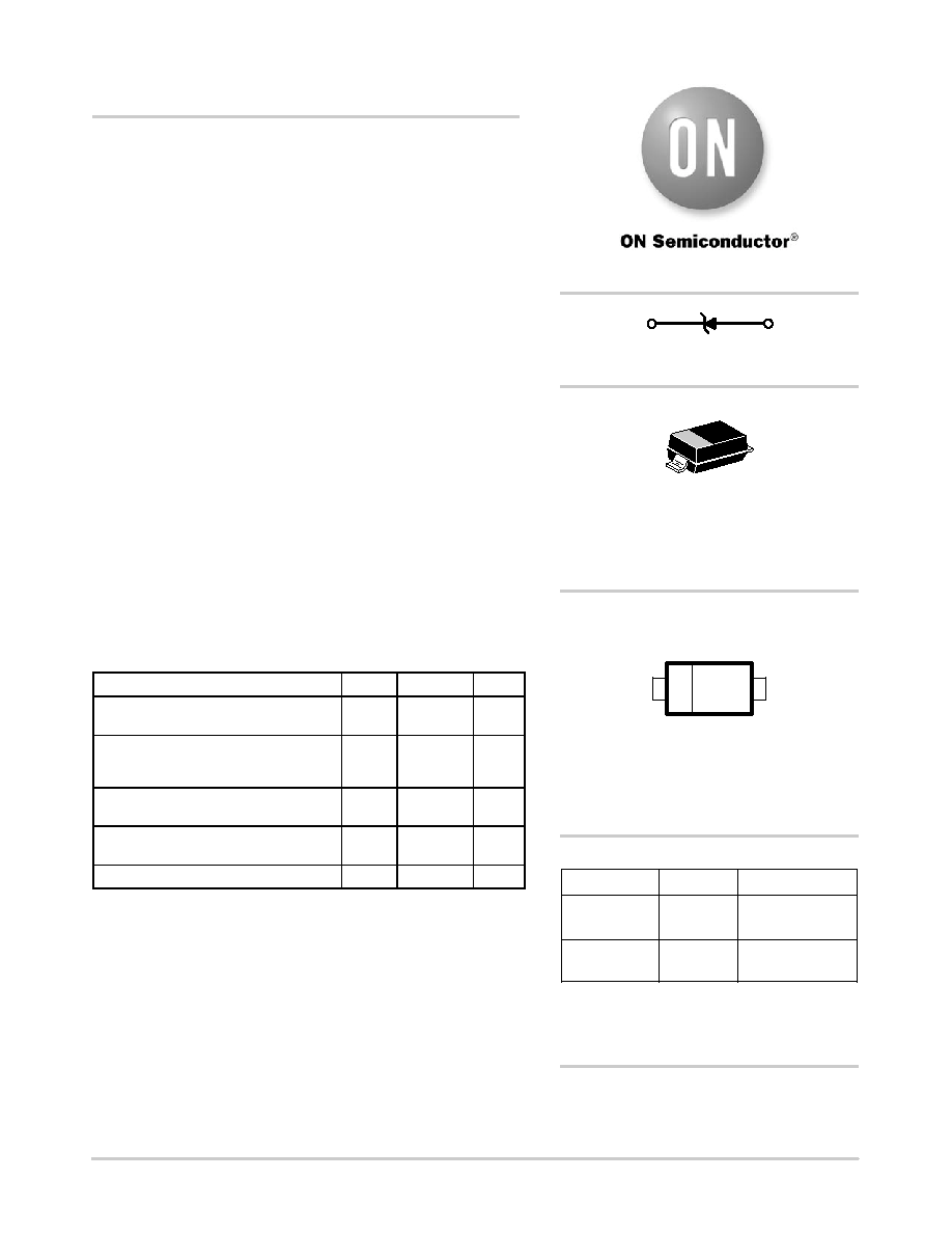
Zener Voltage Regulators
500 mW SOD123 Surface Mount
Three complete series of Zener diodes are offered in the convenient,
surface mount plastic SOD123 package. These devices provide a
convenient alternative to the leadless 34package style.
Specification Features
500 mW Rating on FR4 or FR5 Board
Wide Zener Reverse Voltage Range 2.4 V to 56 V
Package Designed for Optimal Automated Board Assembly
Small Package Size for High Density Applications
ESD Rating of Class 3 (>16 kV) per Human Body Model
Peak Power 225 W (8 X 20 ms)
PbFree Packages are Available
Mechanical Characteristics
CASE:
Void-free, transfer-molded, thermosetting plastic case
FINISH:
Corrosion resistant finish, easily solderable
MAXIMUM CASE TEMPERATURE FOR SOLDERING PURPOSES:
260
°C for 10 Seconds
POLARITY:
Cathode indicated by polarity band
FLAMMABILITY RATING:
UL 94 V0
MAXIMUM RATINGS
Rating
Symbol
Max
Unit
Peak Power Dissipation @ 20
ms (Note 1)
@ TL ≤ 25°C
Ppk
225
W
Total Power Dissipation on FR5 Board,
Derated above 75
°C
PD
500
6.7
mW
mW/
°C
Thermal Resistance, JunctiontoAmbient
(Note 3)
RqJA
340
°C/W
Thermal Resistance, JunctiontoLead
(Note 3)
RqJL
150
°C/W
Junction and Storage Temperature Range
TJ, Tstg
55 to +150
°C
Maximum ratings are those values beyond which device damage can occur.
Maximum ratings applied to the device are individual stress limit values (not
normal operating conditions) and are not valid simultaneously. If these limits are
exceeded, device functional operation is not implied, damage may occur and
reliability may be affected.
1. Nonrepetitive current pulse per Figure 11
2. FR5 = 3.5 X 1.5 inches, using the ON minimum recommended footprint
3. Thermal Resistance measurement obtained via infrared Scan Method
http://onsemi.com
SOD123
CASE 425
STYLE 1
1
Cathode
2
Anode
MARKING DIAGRAM
1
2
Device
Package
Shipping
ORDERING INFORMATION
MMSZxxxET1
SOD123
(PbFree)
3000/Tape & Reel
MMSZxxxET3
SOD123
(PbFree)
10,000/Tape & Reel
For information on tape and reel specifications,
including part orientation and tape sizes, please
refer to our Tape and Reel Packaging Specifications
Brochure, BRD8011/D.
See specific marking information in the device marking
column of the Electrical Characteristics table on page 3 of
DEVICE MARKING INFORMATION
xxx = Device Code
M
= Date Code
G
= PbFree Package
(Note: Microdot may be in either location)
xxx M
G
相关PDF资料 |
PDF描述 |
|---|---|
| MSD6100G | 0.2 A, 100 V, 2 ELEMENT, SILICON, SIGNAL DIODE, TO-226AA |
| MUR440-E3 | 4 A, 400 V, SILICON, RECTIFIER DIODE, DO-201AD |
| MQSMCGLCE9.0AE3TR | 1500 W, UNIDIRECTIONAL, SILICON, TVS DIODE, DO-215AB |
| MQSMCJLCE17E3 | 1500 W, UNIDIRECTIONAL, SILICON, TVS DIODE, DO-214AB |
| MSPSMCGLCE120AE3 | 1500 W, UNIDIRECTIONAL, SILICON, TVS DIODE, DO-215AB |
相关代理商/技术参数 |
参数描述 |
|---|---|
| MMSZ13ET3 | 制造商:ONSEMI 制造商全称:ON Semiconductor 功能描述:Zener Voltage Regulators |
| MMSZ13T1 | 功能描述:稳压二极管 13V 500mW RoHS:否 制造商:Vishay Semiconductors 齐纳电压:12 V 电压容差:5 % 电压温度系数:0.075 % / K 齐纳电流: 功率耗散:3 W 最大反向漏泄电流:3 uA 最大齐纳阻抗:7 Ohms 最大工作温度:+ 150 C 安装风格:SMD/SMT 封装 / 箱体:DO-214AC 封装:Reel |
| MMSZ13T1G | 功能描述:稳压二极管 13V 500mW RoHS:否 制造商:Vishay Semiconductors 齐纳电压:12 V 电压容差:5 % 电压温度系数:0.075 % / K 齐纳电流: 功率耗散:3 W 最大反向漏泄电流:3 uA 最大齐纳阻抗:7 Ohms 最大工作温度:+ 150 C 安装风格:SMD/SMT 封装 / 箱体:DO-214AC 封装:Reel |
| MMSZ13T1H | 制造商:ON Semiconductor 功能描述: |
| MMSZ13T3 | 制造商:ONSEMI 制造商全称:ON Semiconductor 功能描述:Zener Voltage Regulators |
发布紧急采购,3分钟左右您将得到回复。