- 您现在的位置:买卖IC网 > PDF目录95987 > MN101CP52A (PANASONIC CORP) 8-BIT, OTPROM, 20 MHz, MICROCONTROLLER, PQFP64 PDF资料下载
参数资料
| 型号: | MN101CP52A |
| 厂商: | PANASONIC CORP |
| 元件分类: | 微控制器/微处理器 |
| 英文描述: | 8-BIT, OTPROM, 20 MHz, MICROCONTROLLER, PQFP64 |
| 封装: | 14 X 14 MM, LEAD FREE, PLASTIC, LQFP-64 |
| 文件页数: | 2/5页 |
| 文件大小: | 488K |
| 代理商: | MN101CP52A |
2
MN101C527
Timer Counter (Continue)
Timer counter 8: 16-bit
× 1
(square-wave/16-bit PWM output [duty continuous variable], event count, pulse width measurement, input
capture)
(square-wave/PWM output to large current terminal P53 possible)
Clock source 1/1, 1/2, 1/4, 1/16 of system clock frequency;
1/1, 1/2, 1/4, 1/16 of OSC oscillation clock frequency;
1/1, 1/2, 1/4, 1/16 of external clock input frequency
Interrupt source agreement with compare register 8
Timer counters 7, 8 can be cascade-connected.
(square-wave output, input capture, pulse width measurement is possible as a 32-bit timer.)
Time base timer (one-minute count setting)
Clock source 1/1 of OSC oscillation clock frequency; 1/1 of XI oscillation clock frequency
Interrupt source 1/128, 1/256, 1/512, 1/1024, 1/8192, 1/32768 of clock source frequency
Watchdog timer
Interrupt source 1/65536, 1/262144, 1/1048576 of system clock frequency
Serial Interface
Serial 0 : synchronous type/UART (full-duplex)
× 1
Clock source 1/2, 1/4 of system clock frequency; 1/2 pulse output of timer counter 3;
1/2, 1/4, 1/16, 1/64 of OSC oscillation clock frequency
I/O Pins
42
Common use Specified pull-up resistor available Input/output selectable (bit unit)
Specified pull-down resistor partially selectable
I/O
7
Common use Specified pull-up resistor available Specified pull-down resistor partially selectable
Input
A/D Inputs
10-bit
× 4-ch. (with S/H)
LCD
24 segments
× 4 commons (Static, 1/2, 1/3, or 1/4 duty)
LCD power supply separated from VDD (usable if VDD
≤ VLCD ≤ 5.5 V)
LCD power step-up circuit contained (3/2, 2 and 3 times)
LCD shunt resistance contained
Special Ports
Buzzer output, remote control carrier signal output, high-current drive port
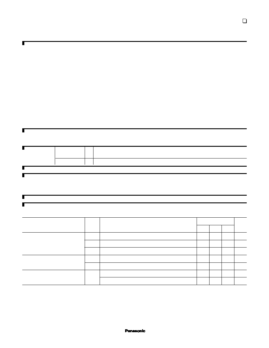
Electrical Characteristics
Supply current
Limit
Symbol
Condition
min
typ
max
Unit
Parameter
IDD1
fosc = 20 MHz, VDD = 5 V
25
60
mA
IDD2
fosc = 8 MHz, VDD = 5 V
10
25
mA
IDD3
fx = 32 kHz, VDD = 3 V
30
100
A
IDD4
fx = 32 kHz, VDD = 3 V, Ta = 25
°C8
A
IDD5
fx = 32 kHz, VDD = 3 V, Ta =
40°C to +85°C
30
A
IDD6
VDD = 5 V, Ta = 25
°C2
A
VDD = 5 V, Ta =
40°C to +85°C35
A
Operating supply current
Supply current at HALT
Supply current at STOP
See the next page for pin assignment and support tool.
MAD00013DEM
Ma
int
en
an
ce
/
Dis
co
nti
nu
ed
Please
visit
following
URL
about
latest
information.
http://panasonic.co.jp/semicon/e-index.html
相关PDF资料 |
PDF描述 |
|---|---|
| MN101DF06K | 8-BIT, FLASH, 14.32 MHz, MICROCONTROLLER, PQFP100 |
| MN101DF06ZAF | 8-BIT, FLASH, 14.32 MHz, MICROCONTROLLER, PQFP100 |
| MN101EF33K | 8-BIT, FLASH, 20 MHz, MICROCONTROLLER, PQFP100 |
| MN102H930F | 16-BIT, MROM, 34 MHz, MICROCONTROLLER, PQFP100 |
| MN102HF51K | 16-BIT, FLASH, 12 MHz, MICROCONTROLLER, PDIP64 |
相关代理商/技术参数 |
参数描述 |
|---|---|
| MN101CP539HT | 制造商:PANASONIC 制造商全称:Panasonic Semiconductor 功能描述:MICROCOMPUTER LSI |
| MN101CP54C | 制造商:PANASONIC 制造商全称:Panasonic Semiconductor 功能描述:Lower limit for operation guarantee for flash memory built-in type is 4.5 V |
| MN101CP66D | 制造商:PANASONIC 制造商全称:Panasonic Semiconductor 功能描述:MN101C66D |
| MN101D01FPA4 | 制造商:Panasonic Industrial Company 功能描述:IC |
| MN101D01GPC1 | 制造商:Panasonic Industrial Company 功能描述:IC |
发布紧急采购,3分钟左右您将得到回复。