- 您现在的位置:买卖IC网 > PDF目录39723 > MP3508W (LITE-ON SEMICONDUCTOR CORP) 35 A, 800 V, SILICON, BRIDGE RECTIFIER DIODE PDF资料下载
参数资料
| 型号: | MP3508W |
| 厂商: | LITE-ON SEMICONDUCTOR CORP |
| 元件分类: | 桥式整流 |
| 英文描述: | 35 A, 800 V, SILICON, BRIDGE RECTIFIER DIODE |
| 封装: | PLASTIC PACKAGE-4 |
| 文件页数: | 1/2页 |
| 文件大小: | 24K |
| 代理商: | MP3508W |
DS21351 Rev. B-3
1 of 2
MP35005/W - MP3510/W
MP35005/W - MP3510/W
35A BRIDGE RECTIFIER
Features
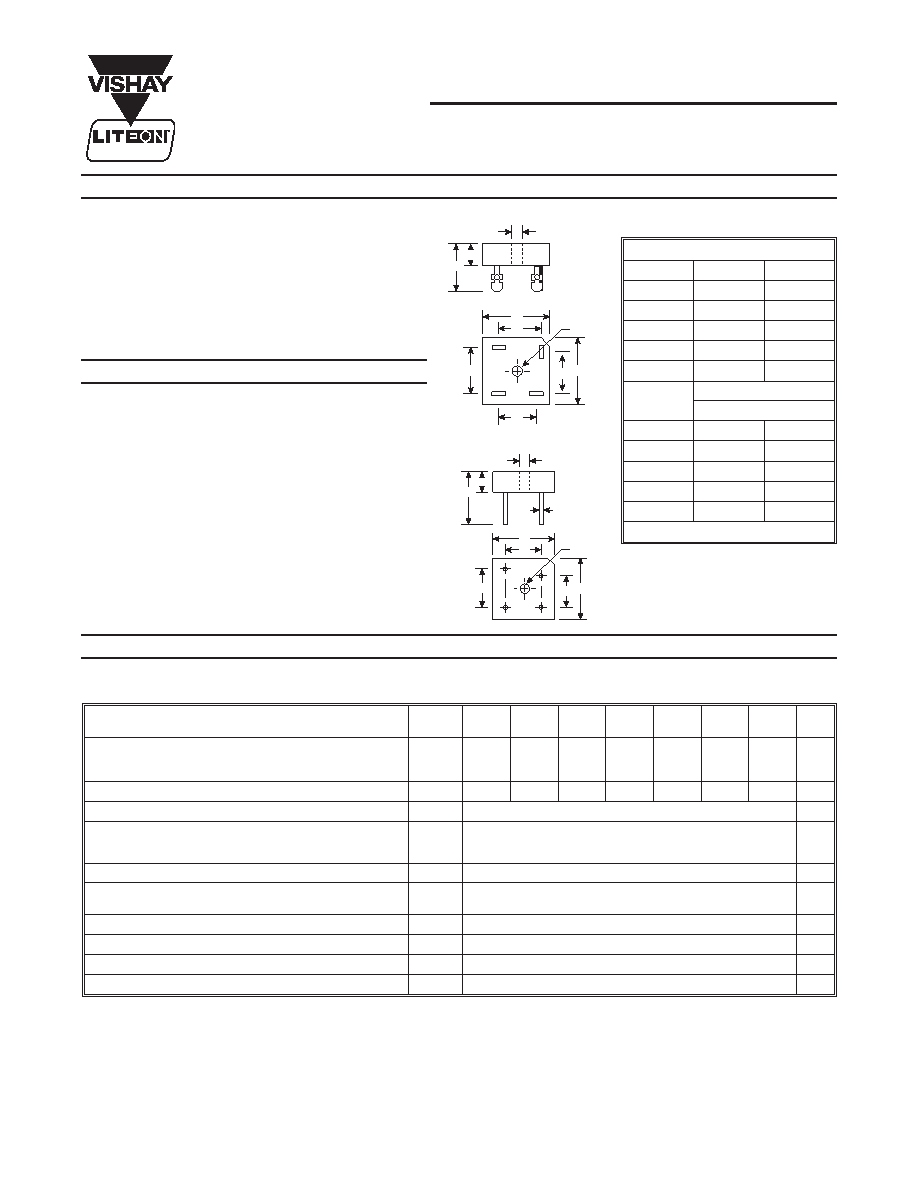
Mechanical Data
MP-W
C
A
G
E
B
H
(AC)
(+)
(-)
H
J
A
C
K
A
M
B
H
L
P
A
P
(AC)
(-)
(+)
MP
W Suffix Designates Wire Leads
No Suffix Designates Faston Terminals
Diffused Junction
Low Reverse Leakage Current
Low Power Loss, High Efficiency
Surge Overload Rating to 400A Peak
Case to Terminal Isolation Voltage 1500V
UL Listed: Recognized Component Index,
File Number E95060
Case: Molded Plastic with Heatsink Internally
Mounted in the Bridge Encapsulation
Terminals: Plated Leads Solderable per
MIL-STD-202, Method 208
Polarity: Symbols Marked on Case
Mounting: Through Hole for #10 Screw
Mounting Torque: 8.0 Inch-pounds Maximum
MP Weight: 23 grams (approx.)
MP-W Weight: 17 grams (approx.)
Mounting Position: Any
Maximum Ratings and Electrical Characteristics @ TA = 25°C unless otherwise specified
Single phase, 60Hz, resistive or inductive load.
For capacitive load, derate current by 20%.
Characteristic
Symbol
MP35
005/W
MP35
01/W
MP35
02/W
MP35
04/W
MP35
06/W
MP35
08/W
MP35
10/W
Unit
Peak Repetitive Reverse Voltage
Working Peak Reverse Voltage
DC Blocking Voltage
VRRM
VRWM
VR
50
100
200
400
600
800
1000
V
RMS Reverse Voltage
VR(RMS)
35
70
140
280
420
560
700
V
Average Rectified Output Current
@ TC = 55
°C
IO
35
A
Non-Repetitive Peak Forward Surge Current,
8.3 ms Single half sine-wave superimposed on rated load
(JEDEC Method)
IFSM
400
A
Forward Voltage (per element)
@ IF = 17.5A
VF
1.1
V
Peak Reverse Current
@ TC = 25
°C
at Rated DC Blocking Voltage
@ TC = 105
°C
IRM
10
0.5
A
mA
I2t Rating for Fusing
(Note 1)
I2t
664
A2s
Typical Junction Capacitance
(Note 2)
Cj
400
pF
Typical Thermal Resistance Junction to Case
(Note 3)
RθJC
3.8
K/W
Operating and Storage Temperature Range
Tj, TSTG
-65 to +125
°C
Notes:
1. Non-repetitive, for t > 1.0ms and t < 8.3ms.
2. Measured at 1.0MHz and applied reverse voltage of 4.0V DC.
3. Thermal resistance junction to case per element mounted on heatsink.
MP / MP-W
Dim
Min
Max
A
28.40
28.70
B
9.70
10.00
C
15.70
16.70
E
22.86
25.40
G
13.50
14.50
H
Hole for #10 screw
5.08
Nominal
J
17.50
18.50
K
10.90
11.90
L
0.97
1.07
M
30.50
—
P
17.60
18.60
All Dimensions in mm
POWER SEMICONDUCTOR
相关PDF资料 |
PDF描述 |
|---|---|
| MP3502W | 35 A, 200 V, SILICON, BRIDGE RECTIFIER DIODE |
| MP3501 | 35 A, 100 V, SILICON, BRIDGE RECTIFIER DIODE |
| MP3505 | 35 A, 400 V, SILICON, BRIDGE RECTIFIER DIODE |
| MP3510W | 35 A, 1000 V, SILICON, BRIDGE RECTIFIER DIODE |
| MP3502W | 35 A, 200 V, SILICON, BRIDGE RECTIFIER DIODE |
相关代理商/技术参数 |
参数描述 |
|---|---|
| MP350-C | 功能描述:电线鉴定 MARKER PLATE RoHS:否 制造商:TE Connectivity / Q-Cees 产品:Labels and Signs 类型: 材料:Vinyl 颜色:Blue 宽度:0.625 in 长度:1 in |
| MP350-C | 制造商:Panduit Corp 功能描述:Marking Plate |
| MP350-C0 | 功能描述:电线鉴定 Marker Plate 3.50" x 0.75" RoHS:否 制造商:TE Connectivity / Q-Cees 产品:Labels and Signs 类型: 材料:Vinyl 颜色:Blue 宽度:0.625 in 长度:1 in |
| MP350-M | 功能描述:电线鉴定 MARKER PLATE RoHS:否 制造商:TE Connectivity / Q-Cees 产品:Labels and Signs 类型: 材料:Vinyl 颜色:Blue 宽度:0.625 in 长度:1 in |
| MP350-M0 | 制造商:Panduit Corp 功能描述: |
发布紧急采购,3分钟左右您将得到回复。