- 您现在的位置:买卖IC网 > PDF目录80545 > MPC8548EHXATJB (FREESCALE SEMICONDUCTOR INC) 32-BIT, 1200 MHz, MICROPROCESSOR, CBGA783 PDF资料下载
参数资料
| 型号: | MPC8548EHXATJB |
| 厂商: | FREESCALE SEMICONDUCTOR INC |
| 元件分类: | 微控制器/微处理器 |
| 英文描述: | 32-BIT, 1200 MHz, MICROPROCESSOR, CBGA783 |
| 封装: | 29 X 29 MM, 1 MM PITCH, FLIP CHIP, CERAMIC, BGA-783 |
| 文件页数: | 111/142页 |
| 文件大小: | 1504K |
| 代理商: | MPC8548EHXATJB |
第1页第2页第3页第4页第5页第6页第7页第8页第9页第10页第11页第12页第13页第14页第15页第16页第17页第18页第19页第20页第21页第22页第23页第24页第25页第26页第27页第28页第29页第30页第31页第32页第33页第34页第35页第36页第37页第38页第39页第40页第41页第42页第43页第44页第45页第46页第47页第48页第49页第50页第51页第52页第53页第54页第55页第56页第57页第58页第59页第60页第61页第62页第63页第64页第65页第66页第67页第68页第69页第70页第71页第72页第73页第74页第75页第76页第77页第78页第79页第80页第81页第82页第83页第84页第85页第86页第87页第88页第89页第90页第91页第92页第93页第94页第95页第96页第97页第98页第99页第100页第101页第102页第103页第104页第105页第106页第107页第108页第109页第110页当前第111页第112页第113页第114页第115页第116页第117页第118页第119页第120页第121页第122页第123页第124页第125页第126页第127页第128页第129页第130页第131页第132页第133页第134页第135页第136页第137页第138页第139页第140页第141页第142页
MPC8548E PowerQUICC III Integrated Processor Hardware Specifications, Rev. 5
70
Freescale Semiconductor
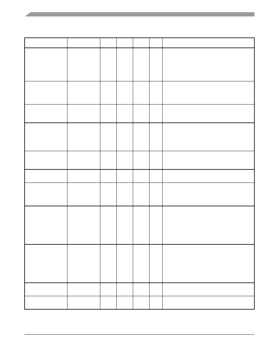
PCI Express
VTX-CM-DC-ACTIVE-
IDLE-DELTA
Absolute delta of
dc common
mode voltage
during L0 and
electrical idle
0—
100
mV
|VTX-CM-DC (during L0) + VTX-CM-Idle-DC (during
electrical idle)| <= 100 mV
VTX-CM-DC = DC(avg) of |VTX-D+ + VTX-D–|/2 [L0]
VTX-CM-Idle-DC = DC(avg) of |VTX-D+ +VTX-D–|/2
[electrical idle]
See Note 2.
VTX-CM-DC-LINE-DELTA Absolute delta of
DC common
mode between
D+ and D–
0—
25
mV
|VTX-CM-DC-D+ – VTX-CM-DC-D–| <= 25 mV
VTX-CM-DC-D+ = DC(avg) of |VTX-D+|
VTX-CM-DC-D–= DC(avg) of |VTX-D–|.
See Note 2.
VTX-IDLE-DIFFp
Electrical idle
differential peak
output voltage
0—
20
mV
VTX-IDLE-DIFFp = |VTX-IDLE-D+ – VTX-IDLE-D–|
<= 20 mV.
See Note 2.
VTX-RCV-DETECT
The amount of
voltage change
allowed during
receiver
detection
—
600
mV
The total amount of voltage change that a
transmitter can apply to sense whether a low
impedance receiver is present. See Note 6.
VTX-DC-CM
The TX DC
common mode
voltage
0
—
3.6
V
The allowed DC common mode voltage under any
conditions. See Note 6.
ITX-SHORT
TX short circuit
current limit
—
90
mA
The total current the transmitter can provide when
shorted to its ground
TTX-IDLE-MIN
Minimum time
spent in
electrical idle
50
—
UI
Minimum time a transmitter must be in electrical
idle utilized by the receiver to start looking for an
electrical idle exit after successfully receiving an
electrical idle ordered set
TTX-IDLE-SET-TO-IDLE
Maximum time
to transition to a
valid electrical
idle after
sending an
electrical idle
ordered set
—
20
UI
After sending an electrical idle ordered set, the
transmitter must meet all electrical idle
specifications within this time. This is considered
a debounce time for the transmitter to meet
electrical idle after transitioning from L0.
TTX-IDLE-TO-DIFF-DATA
Maximum time
to transition to
valid TX
specifications
after leaving an
electrical idle
condition
—
20
UI
Maximum time to meet all TX specifications when
transitioning from electrical idle to sending
differential data. This is considered a debounce
time for the TX to meet all TX specifications after
leaving electrical idle
RLTX-DIFF
Differential
return loss
12
—
dB
Measured over 50 MHz to 1.25 GHz.
See Note 4.
RLTX-CM
Common mode
return loss
6
—
dB
Measured over 50 MHz to 1.25 GHz.
See Note 4.
Table 52. Differential Transmitter (TX) Output Specifications (continued)
Symbol
Parameter
Min
Nom
Max
Unit
Comments
相关PDF资料 |
PDF描述 |
|---|---|
| MPC8548EPXAUGB | 32-BIT, 1333 MHz, MICROPROCESSOR, PBGA783 |
| MPC8548EVUATJA | 32-BIT, 1200 MHz, MICROPROCESSOR, CBGA783 |
| MSP430CG4617IZQW | 16-BIT, FLASH, 8 MHz, RISC MICROCONTROLLER, PBGA113 |
| MC9S08QG44CDTE | 8-BIT, FLASH, 20 MHz, MICROCONTROLLER, PDSO16 |
| MC9S08DN16VLC | 8-BIT, FLASH, 16 MHz, MICROCONTROLLER, PQFP32 |
相关代理商/技术参数 |
参数描述 |
|---|---|
| MPC8548EHXAUJ | 功能描述:微处理器 - MPU PQ38 8548E RoHS:否 制造商:Atmel 处理器系列:SAMA5D31 核心:ARM Cortex A5 数据总线宽度:32 bit 最大时钟频率:536 MHz 程序存储器大小:32 KB 数据 RAM 大小:128 KB 接口类型:CAN, Ethernet, LIN, SPI,TWI, UART, USB 工作电源电压:1.8 V to 3.3 V 最大工作温度:+ 85 C 安装风格:SMD/SMT 封装 / 箱体:FBGA-324 |
| MPC8548EHXAVH | 制造商:Freescale Semiconductor 功能描述:MPU RISC 32BIT CMOS 1.5GHZ 1.8V/2.5V/3.3V - Bulk |
| MPC8548EHXAVK | 制造商:Freescale Semiconductor 功能描述:PQ38 8548E - Bulk |
| MPC8548EPXANJB | 制造商:Freescale Semiconductor 功能描述:PQ38 8548 - Bulk |
| MPC8548EPXAQGA | 制造商:Freescale Semiconductor 功能描述:MPC85XX RISC 32-BIT CMOS 1GHZ 1.8V/2.5V/3.3V 783-PIN BGA TRA - Bulk |
发布紧急采购,3分钟左右您将得到回复。