- 您现在的位置:买卖IC网 > PDF目录4099 > MPC885ZP80 (Freescale Semiconductor)IC MPU POWERQUICC 80MHZ 357PBGA PDF资料下载
参数资料
| 型号: | MPC885ZP80 |
| 厂商: | Freescale Semiconductor |
| 文件页数: | 5/87页 |
| 文件大小: | 0K |
| 描述: | IC MPU POWERQUICC 80MHZ 357PBGA |
| 标准包装: | 44 |
| 系列: | MPC8xx |
| 处理器类型: | 32-位 MPC8xx PowerQUICC |
| 速度: | 80MHz |
| 电压: | 3.3V |
| 安装类型: | 表面贴装 |
| 封装/外壳: | 357-BBGA |
| 供应商设备封装: | 357-PBGA(25x25) |
| 包装: | 托盘 |
第1页第2页第3页第4页当前第5页第6页第7页第8页第9页第10页第11页第12页第13页第14页第15页第16页第17页第18页第19页第20页第21页第22页第23页第24页第25页第26页第27页第28页第29页第30页第31页第32页第33页第34页第35页第36页第37页第38页第39页第40页第41页第42页第43页第44页第45页第46页第47页第48页第49页第50页第51页第52页第53页第54页第55页第56页第57页第58页第59页第60页第61页第62页第63页第64页第65页第66页第67页第68页第69页第70页第71页第72页第73页第74页第75页第76页第77页第78页第79页第80页第81页第82页第83页第84页第85页第86页第87页
MPC885/MPC880 PowerQUICC Hardware Specifications, Rev. 7
Freescale Semiconductor
13
Thermal Calculation and Measurement
7.2
Estimation with Junction-to-Case Thermal Resistance
Historically, thermal resistance has frequently been expressed as the sum of a junction-to-case thermal
resistance and a case-to-ambient thermal resistance:
RθJA = RθJC + RθCA
where:
RθJA = junction-to-ambient thermal resistance (C/W)
RθJC = junction-to-case thermal resistance (C/W)
RθCA = case-to-ambient thermal resistance (C/W)
RθJC is device-related and cannot be influenced by the user. The user adjusts the thermal environment to
affect the case-to-ambient thermal resistance, RθCA. For instance, the user can change the airflow around
the device, add a heat sink, change the mounting arrangement on the printed-circuit board, or change the
thermal dissipation on the printed-circuit board surrounding the device. This thermal model is most useful
for ceramic packages with heat sinks where some 90% of the heat flows through the case and the heat sink
to the ambient environment. For most packages, a better model is required.
7.3
Estimation with Junction-to-Board Thermal Resistance
A simple package thermal model that has demonstrated reasonable accuracy (about 20%) is a two-resistor
model consisting of a junction-to-board and a junction-to-case thermal resistance. The junction-to-case
covers the situation where a heat sink is used or where a substantial amount of heat is dissipated from the
top of the package. The junction-to-board thermal resistance describes the thermal performance when most
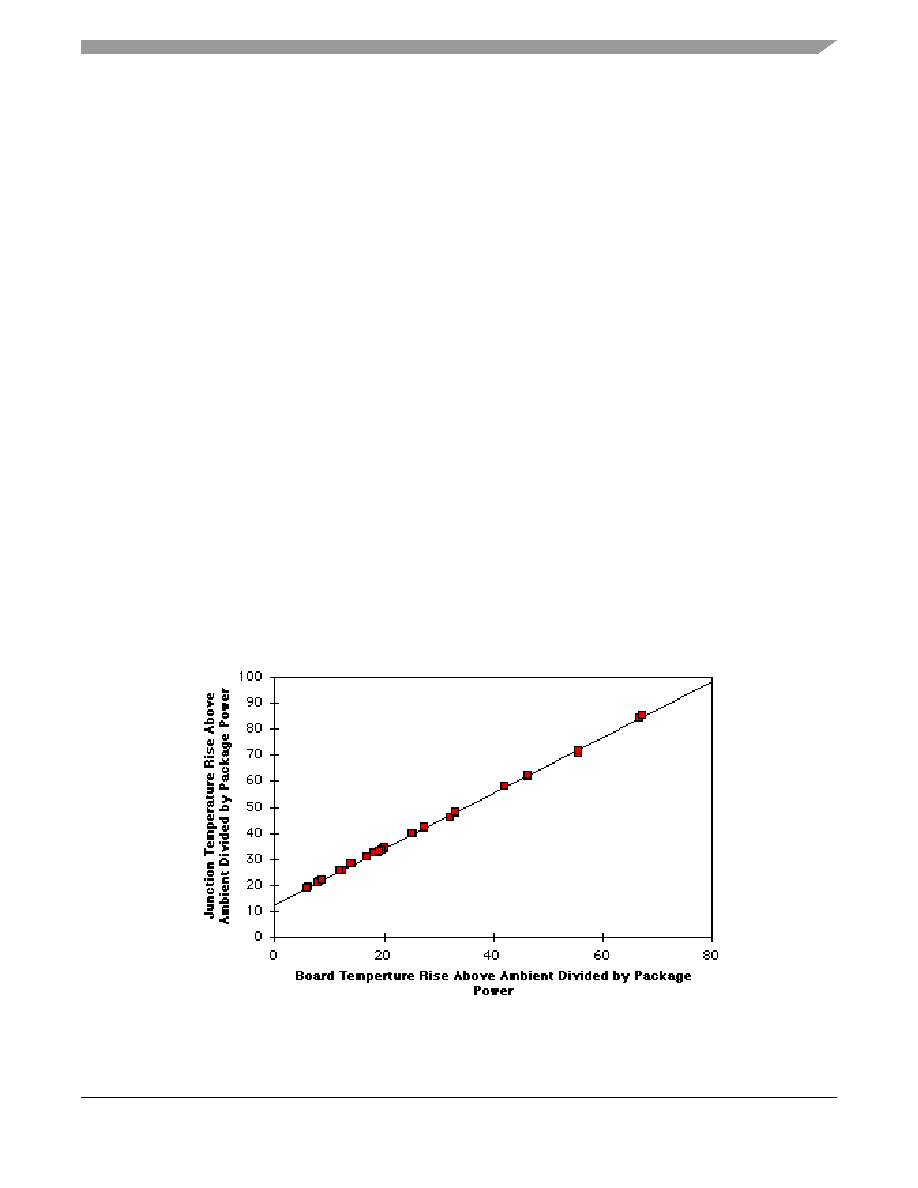
of the heat is conducted to the printed-circuit board. It has been observed that the thermal performance of
most plastic packages and especially PBGA packages is strongly dependent on the board temperature; see
Figure 4. Effect of Board Temperature Rise on Thermal Behavior
相关PDF资料 |
PDF描述 |
|---|---|
| AMM36DTAI-S189 | CONN EDGECARD 72POS R/A .156 SLD |
| MPC8313CZQAFFB | IC MPU POWERQUICC II PRO 516PBGA |
| IDT7143SA20J8 | IC SRAM 32KBIT 20NS 68PLCC |
| FMC30DRYI-S93 | CONN EDGECARD 60POS .100 DIP SLD |
| MPC8313EZQAFFB | IC MPU POWERQUICC II PRO 516PBGA |
相关代理商/技术参数 |
参数描述 |
|---|---|
| MPC-8890 | 制造商:AAEON 制造商全称:AAEON 功能描述:Intel Pentium M or Celeron M Processors |
| MPC-8890-A10 | 制造商:AAEON 制造商全称:AAEON 功能描述:Intel Pentium M or Celeron M Processors |
| MPC-8890-A10-01 | 制造商:AAEON 制造商全称:AAEON 功能描述:Intel Pentium M or Celeron M Processors |
| MPC-8890-A10-02 | 制造商:AAEON 制造商全称:AAEON 功能描述:Intel Pentium M or Celeron M Processors |
| MPC-8890-A10-03 | 制造商:AAEON 制造商全称:AAEON 功能描述:Intel Pentium M or Celeron M Processors |
发布紧急采购,3分钟左右您将得到回复。