- 您现在的位置:买卖IC网 > PDF目录2100 > MPR084QR2 (Freescale Semiconductor)IC CTLR TOUCH SENSOR PROX 16-QFN PDF资料下载
参数资料
| 型号: | MPR084QR2 |
| 厂商: | Freescale Semiconductor |
| 文件页数: | 9/40页 |
| 文件大小: | 0K |
| 描述: | IC CTLR TOUCH SENSOR PROX 16-QFN |
| 标准包装: | 2,500 |
| 类型: | 电容性 |
| 输入数/键: | 8 键 |
| 评估套件: | 可供 |
| 数据接口: | I²C,串行 |
| 电源电压: | 1.8 V ~ 3.6 V |
| 电流 - 电源: | 1.62mA |
| 工作温度: | -40°C ~ 85°C |
| 安装类型: | 表面贴装 |
| 封装/外壳: | 16-VQFN 裸露焊盘 |
| 供应商设备封装: | 16-QFN-EP(5x5) |
| 包装: | 带卷 (TR) |
| 配用: | KITMPR084EVM-ND - KIT EVAL 8-PAD TOUCH MPR084 |
第1页第2页第3页第4页第5页第6页第7页第8页当前第9页第10页第11页第12页第13页第14页第15页第16页第17页第18页第19页第20页第21页第22页第23页第24页第25页第26页第27页第28页第29页第30页第31页第32页第33页第34页第35页第36页第37页第38页第39页第40页
MPR084
Sensors
Freescale Semiconductor
17
5
Low Power Configuration
5.1
Introduction
The MPR084 features a Low Power mode that can reduce the power consumption into the microamps range. This feature can
be used to both adjust the response time of the system, and change the conditions on which Low Power would be enabled.
5.2
Operation
This Low Power configuration is only active when the sensor controller is in Run2 mode. The Low Power mode decreases current
consumption by increasing the response time of the MPR084. This increase is controlled through two factors.
During normal Run2 operation of the sensor controller the Max Response Time (MRT) is calculated by taking the product of the
TASP and the primary clock. From Chapter 4 the primary clock is the (MTP + 5) ms. Since the sensor controller is in Run2, the
primary clock is also multiplied by a factor of 8. The debounce rate of the MPR084 is 4 times the sample rate thus the MRT is
represented by the following equation.
Equation 1
First, the Idle Interface Timeout (IIT) represents the total time the touch interface should remain idle before going into Low Power
mode. This value can be calculated by taking the product of the ITP, TASP and primary clock (8ms) with a factor of 64. Thus the
IIT is represented as follows:
Equation 2
Second, the Max Response Time (MRT) represents the total time the touch interface should remain inactive before scanning the
electrodes. This value can be calculated by taking the product of the SCD, TASP and primary clock (8ms) with a factor of 5. Thus
the MRT is represented as follows:
Equation 3
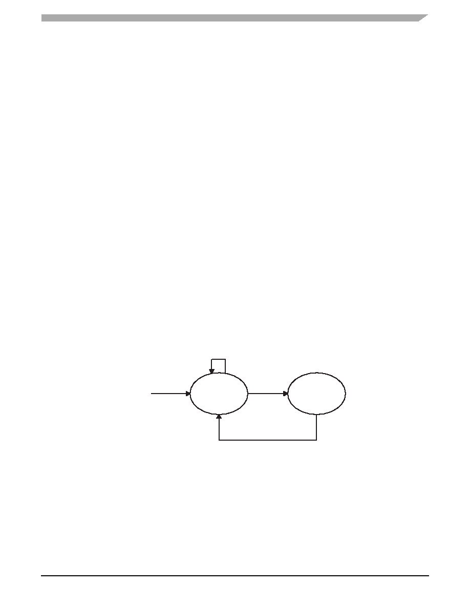
When in Run2 mode, the sensor controller will initially scan the electrodes at the rate of MRT1. When scanning at MRT1 and the
touch interface remains idle for the IIT period then the scan period will change to MRT2. When scanning at MRT2 and a touch is
detected the scan rate will transition back to MRT1.
Figure 20. Low Power Scan Period Transition Diagram
5.3
Configuration
Low Power Configuration is achieved through setting two values; the Idle Timeout Period and the Sleep Cycle Duration. This
functionality is described in the following section.
MRT1
MTP
5
+
8
----------------------
1
+
TASP
48ms
=
MRT2
MTP
5
+
8
----------------------
1
+
TASP
SCD
48
ms
=
ITT
MTP
5
+
8
----------------------
1
+
TASP
ITP
68ms
=
LP DISABLED
ITT PERIOD
run2 SET
TOUCH DETECTED
MRT1
MRT2
相关PDF资料 |
PDF描述 |
|---|---|
| MPR121QR2 | IC CTLR TOUCH SENSOR 20-QFN |
| MX674ALCWI+T | IC ADC 12BIT W/REF 28-SOIC |
| MX7575KN+ | IC ADC 8BIT MPU COMP 18-DIP |
| MX7582KN+ | IC ADC 12BIT 4CH 28-DIP |
| MX7705EWE+ | IC ADC 16BIT 2CH 16-SOIC |
相关代理商/技术参数 |
参数描述 |
|---|---|
| MPR0854FPXXXZ01A | 功能描述:AC/DC CONVERTER 54V 800W 制造商:ge critical power 系列:MPR,耐火 零件状态:有效 类型:前端 输出数:1 电压 - 输入:90 ~ 264 VAC 电压 - 输出 1:54V 电压 - 输出 2:- 电压 - 输出 3:- 电压 - 输出 4:- 电流 - 输出(最大值):14.8A 功率(W):800W 应用:ITE(商业) 电压 - 隔离:3kV(3000V) 效率:88% 工作温度:-10°C ~ 70°C(有降额) 特性:热插拔,I2C? 接口,负载均分,PFC,PMBus?,远程开/关,遥测,待机输出,通用输入 安装类型:机架安装 大小/尺寸:8.93" 长 x 3.40" 宽 x 1.57" 高(226.8mm x 86.4mm x 39.9mm) 所需最小负载:无 认可:- 功率(W) - 最大值:800W 标准包装:5 |
| MPR106M2 | 制造商:DEARBORN ELECTRONICS INC 功能描述:CAPACITOR MILITARY FILM |
| MPR106M2S1 | 制造商:SPEC 功能描述: 制造商:Vishay Sprague 功能描述: |
| MPR10JB50L0 | 制造商:SEI Stackpole Electronics Inc 功能描述:- Bulk 制造商:SEI Stackpole Electronics Inc 功能描述:MPR10JB50L0 |
| MPR10JB75L0 | 制造商:SEI Stackpole Electronics Inc 功能描述:- Bulk 制造商:SEI Stackpole Electronics Inc 功能描述:MPR10JB75L0 |
发布紧急采购,3分钟左右您将得到回复。