- 您现在的位置:买卖IC网 > PDF目录80340 > MQ80C52TXXX-16SB (TEMIC SEMICONDUCTORS) 8-BIT, MROM, 16 MHz, MICROCONTROLLER, CQFP44 PDF资料下载
参数资料
| 型号: | MQ80C52TXXX-16SB |
| 厂商: | TEMIC SEMICONDUCTORS |
| 元件分类: | 微控制器/微处理器 |
| 英文描述: | 8-BIT, MROM, 16 MHz, MICROCONTROLLER, CQFP44 |
| 文件页数: | 216/287页 |
| 文件大小: | 12910K |
| 代理商: | MQ80C52TXXX-16SB |
第1页第2页第3页第4页第5页第6页第7页第8页第9页第10页第11页第12页第13页第14页第15页第16页第17页第18页第19页第20页第21页第22页第23页第24页第25页第26页第27页第28页第29页第30页第31页第32页第33页第34页第35页第36页第37页第38页第39页第40页第41页第42页第43页第44页第45页第46页第47页第48页第49页第50页第51页第52页第53页第54页第55页第56页第57页第58页第59页第60页第61页第62页第63页第64页第65页第66页第67页第68页第69页第70页第71页第72页第73页第74页第75页第76页第77页第78页第79页第80页第81页第82页第83页第84页第85页第86页第87页第88页第89页第90页第91页第92页第93页第94页第95页第96页第97页第98页第99页第100页第101页第102页第103页第104页第105页第106页第107页第108页第109页第110页第111页第112页第113页第114页第115页第116页第117页第118页第119页第120页第121页第122页第123页第124页第125页第126页第127页第128页第129页第130页第131页第132页第133页第134页第135页第136页第137页第138页第139页第140页第141页第142页第143页第144页第145页第146页第147页第148页第149页第150页第151页第152页第153页第154页第155页第156页第157页第158页第159页第160页第161页第162页第163页第164页第165页第166页第167页第168页第169页第170页第171页第172页第173页第174页第175页第176页第177页第178页第179页第180页第181页第182页第183页第184页第185页第186页第187页第188页第189页第190页第191页第192页第193页第194页第195页第196页第197页第198页第199页第200页第201页第202页第203页第204页第205页第206页第207页第208页第209页第210页第211页第212页第213页第214页第215页当前第216页第217页第218页第219页第220页第221页第222页第223页第224页第225页第226页第227页第228页第229页第230页第231页第232页第233页第234页第235页第236页第237页第238页第239页第240页第241页第242页第243页第244页第245页第246页第247页第248页第249页第250页第251页第252页第253页第254页第255页第256页第257页第258页第259页第260页第261页第262页第263页第264页第265页第266页第267页第268页第269页第270页第271页第272页第273页第274页第275页第276页第277页第278页第279页第280页第281页第282页第283页第284页第285页第286页第287页
34
8011Q–AVR–02/2013
ATmega164P/324P/644P
Notes:
1. These options should only be used when not operating close to the maximum frequency of the
device, and only if frequency stability at start-up is not important for the application. These
options are not suitable for crystals.
2. These options are intended for use with ceramic resonators and will ensure frequency stability
at start-up. They can also be used with crystals when not operating close to the maximum fre-
quency of the device, and if frequency stability at start-up is not important for the application.
6.5
Low Frequency Crystal Oscillator
The Low-frequency Crystal Oscillator is optimized for use with a 32.768 kHz watch crystal.
When selecting crystals, load capasitance and crystal’s Equivalent Series Resistance, ESR
must be taken into consideration. Both values are specified by the crystal vendor.
ATmega164P/324P/644P oscillator is optimized for very low power consumption, and thus when
selecting crystals, see Table 6-7 on page 34 for maximum ESR recommendations on 9 pF and
12.5 pF crystals
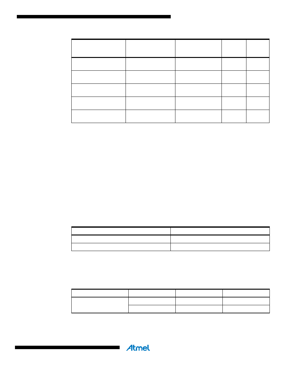
Table 6-7.
Maximum ESR Recommendation for 32.768 kHz Watch Crystal
Note:
1. Maximum ESR is typical value based on characterization
The Low-frequency Crystal Oscillator provides an internal load capacitance, seeTable 6-8 on
page 34 at each TOSC pin.
Table 6-8.
Capasitance for Low-frequency Oscillator.
Ceramic resonator, fast
rising power
1K CK
14CK + 4.1 ms(2)
011
Ceramic resonator, slowly
rising power
1K CK
14CK + 65 ms(2)
100
Crystal Oscillator, BOD
enabled
16K CK
14CK
1
01
Crystal Oscillator, fast
rising power
16K CK
14CK + 4.1 ms
1
10
Crystal Oscillator, slowly
rising power
16K CK
14CK + 65 ms
1
11
Table 6-6.
Start-up Times for the Full Swing Crystal Oscillator Clock Selection
Oscillator Source /
Power Conditions
Start-up Time from
Power-down and
Power-save
Additional Delay
from Reset
(V
CC = 5.0V)
CKSEL0
SUT1..0
Crystal CL (pF)
Max ESR [k
](1)
9.0
65
12.5
30
Device
32 kHz Osc. Type
Cap(Xtal1/Tosc1)
Cap(Xtal2/Tosc2)
ATmega164P/324P/644P
System Osc.
18 pF
8 pF
Timer Osc.
6 pF
相关PDF资料 |
PDF描述 |
|---|---|
| MQ80C52XXX-20SCR | 8-BIT, MROM, 20 MHz, MICROCONTROLLER, CQFP44 |
| MR80C32E-30SBR | 8-BIT, 30 MHz, MICROCONTROLLER, CQCC44 |
| MD80C52EXXX-36/883D | 8-BIT, MROM, 36 MHz, MICROCONTROLLER, CDIP40 |
| MD80C52TXXX-36P883D | 8-BIT, MROM, 36 MHz, MICROCONTROLLER, CDIP40 |
| MR80C32-36SC | 8-BIT, 36 MHz, MICROCONTROLLER, CQCC44 |
相关代理商/技术参数 |
参数描述 |
|---|---|
| MQ82370-20 | 制造商:Rochester Electronics LLC 功能描述:- Bulk |
| MQ8238020 | 制造商:Intel 功能描述:CONTROLLER: OTHER |
| MQ82380-20 | 制造商:Rochester Electronics LLC 功能描述:- Bulk |
| MQ82380-20/R | 制造商:Rochester Electronics LLC 功能描述: |
| MQ82592 | 制造商:Rochester Electronics LLC 功能描述:- Bulk |
发布紧急采购,3分钟左右您将得到回复。