- 您现在的位置:买卖IC网 > PDF目录385636 > MS-156-C(LP)-2 (Hirose Electric USA, INC.) Subminiature Coaxial Switch 1.6 mm High, DC to 6 GHz PDF资料下载
参数资料
| 型号: | MS-156-C(LP)-2 |
| 厂商: | Hirose Electric USA, INC. |
| 英文描述: | Subminiature Coaxial Switch 1.6 mm High, DC to 6 GHz |
| 中文描述: | 微型同轴开关1.6毫米高,直流到6GHz |
| 文件页数: | 8/8页 |
| 文件大小: | 581K |
| 代理商: | MS-156-C(LP)-2 |
8
B
Precautions
1. Care should be taken to avoid accumulation of moisture inside the mounted receptacle after the washing
process.
2. This product is intended to be used for circuit inspection only. Consult factory if any other application is
considered.
3. The corresponding plug should be inserted in direction perpendicular to the switch mounting surface,
within an angle of 2°. The push-in force should be kept within 6-10 N.
4. Do not use hand soldering for mounting on the board. Doing so could result in solder and flux wicking to
the contact portion.
5. When using a heat gun, hotplate, or similar methods, limit the temperature to 260 applied for 10
seconds max.
6. Consult Hirose if your application, installation methods or end-user environment are different than the
recommended.
B
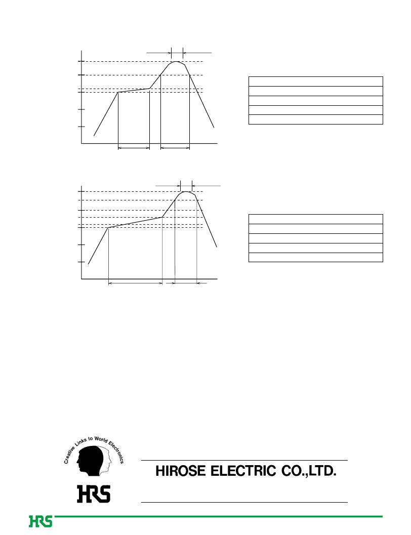
Recommended Temperature Profile
10 sec.max.
Temperature ()
50
0
100
150
160
200
240
40 sec.min.
50 sec.max.
Time (sec.)
q
Maximum temperature
w
Peak temperature time
e
Peak temperature
r
200 min.
t
150 to 160
Metal mask thickness
Reflow cycles
: 0.12 mm
: 2 cycles
: 240
: 10 sec. max.
: 220 to 235
: 50 sec. max.
: 40 sec. min.
Using Typical Solder Paste
q
Maximum temperature
w
Peak temperature time
e
Peak temperature
r
230 min.
t
150 to 180
Metal mask thickness
Reflow cycles
: 0.12 mm
: 2 cycles
: 250
: 10 sec. max.
: 245 to 250
: 30 sec. max.
: 60 sec. min.
Using Lead-free Solder paste
30 sec.max.
Temperature ()
50
0
100
150
160
200
180
230
250
60 sec.min.
Time (sec.)
10 sec.max.
The contents of this catalog are current as of date of publication. Contents are subject to change without notice for the purpose of improvements.
5-23,OSAKI 5-CHOME,SHINAGAWA-KU,TOKYO 141-8587,JAPAN
PHONE: 81-3-3491-9741, FAX: 81-3-3493-2933
http://www.hirose.com
相关PDF资料 |
PDF描述 |
|---|---|
| MS-156LP-HRMJ-1 | Subminiature Coaxial Switch 1.6 mm High, DC to 6 GHz |
| MS-156 | Subminiature Coaxial Switch 1.6 mm High, DC to 6 GHz |
| MS-156(02) | Subminiature Coaxial Switch 1.6 mm High, DC to 6 GHz |
| MS-156-HRMJ-2 | Subminiature Coaxial Switch 1.6 mm High, DC to 6 GHz |
| MS-156-HRMJ-3 | Subminiature Coaxial Switch 1.6 mm High, DC to 6 GHz |
相关代理商/技术参数 |
参数描述 |
|---|---|
| MS-156-CLP-2 | 制造商:HRS 制造商全称:HRS 功能描述:Subminiature Coaxial Switch 1.6 mm High, DC to 6 GHz |
| MS156CLP-HRMJ068V100A | 制造商:Hirose 功能描述: |
| MS156CLP-HRMJ-068V180 | 制造商:Hirose 功能描述: |
| MS156CLP-HRMJ-068V200 | 制造商:Hirose 功能描述:362-0215-8 02 |
| MS156CLP-HRMJ068V50 | 制造商:Hirose 功能描述: |
发布紧急采购,3分钟左右您将得到回复。