- 您现在的位置:买卖IC网 > PDF目录296638 > MSK5940-5.0HRHTS (MS KENNEDY CORP) 5 V FIXED NEGATIVE LDO REGULATOR, 1 V DROPOUT, SFM3 PDF资料下载
参数资料
| 型号: | MSK5940-5.0HRHTS |
| 厂商: | MS KENNEDY CORP |
| 元件分类: | 固定负电压单路输出LDO稳压器 |
| 英文描述: | 5 V FIXED NEGATIVE LDO REGULATOR, 1 V DROPOUT, SFM3 |
| 封装: | STRAIGHT, SIP-3 |
| 文件页数: | 3/6页 |
| 文件大小: | 284K |
| 代理商: | MSK5940-5.0HRHTS |
APPLICATION NOTES
HEAT SINKING
To determine if a heat sink is required for your application and
if so, what type, refer to the thermal model and governing equa-
tion below.
Governing Equation: Tj = Pd x (Rθjc + Rθcs + Rθsa) + Ta
WHERE
Tj = Junction Temperature
Pd = Total Power Dissipation
Rθjc = Junction to Case Thermal Resistance
Rθcs = Case to Heat Sink Thermal Resistance
Rθsa = Heat Sink to Ambient Thermal Resistance
Tc = Case Temperature
Ta = Ambient Temperature
Ts = Heat Sink Temperature
EXAMPLE:
This example demonstrates an analysis where the regulator is at
one-half of its maximum rated power dissipation, which occurs
when the output current is at 1.5 amps.
Conditions for MSK 5940-5RH:
Vin = -7.0V; Iout = -1.5A
1.) Assume 45° heat spreading model.
2.) Find regulator power dissipation:
Pd = (Vin - Vout)(Iout)
Pd = (-7-(-5))(-1.5)
= 3.0W
3.) For conservative design, set Tj = +125°C Max.
4.) For this example, worst case Ta = +90°C.
5.) Rθjc = 7.2°C/W from the Electrical Specification Table.
6.) Rθcs = 0.15°C/W for most thermal greases.
7.) Rearrange governing equation to solve for Rθsa:
Rθsa =
((Tj - Ta)/Pd) - (Rθjc) - (Rθcs)
=
((125°C - 90°C)/3.0W) - 7.2°C/W - 0.15°C/W
=
4.3°C/W
In this case the result is 4.3°C/W. Therefore, a heat sink with a
thermal resistance of no more than 4.3°C/W must be used in this
application to maintain the regulator junction temperature under
125°C.
OVERLOAD SHUTDOWN
The MSK 5940RH features both power and thermal overload
protection. When the maximum power dissipation is not ex-
ceeded, the regulator will current limit slightly above its 3 amp
rating. As the Vin-Vout voltage increases, however, shutdown
occurs in relation to the maximum power dissipation curve. If
the device heats enough to exceed its rated die junction tem-
perature due to excessive ambient temperature, improper heat
sinking etc., the regulator will shutdown until an appropriate
junction temperature is maintained. It should also be noted that
in the case of an extreme overload, such as a sustained direct
short, the device may not be able to recover. In these instances,
the device must be shut off and power reapplied to eliminate the
shutdown condition.
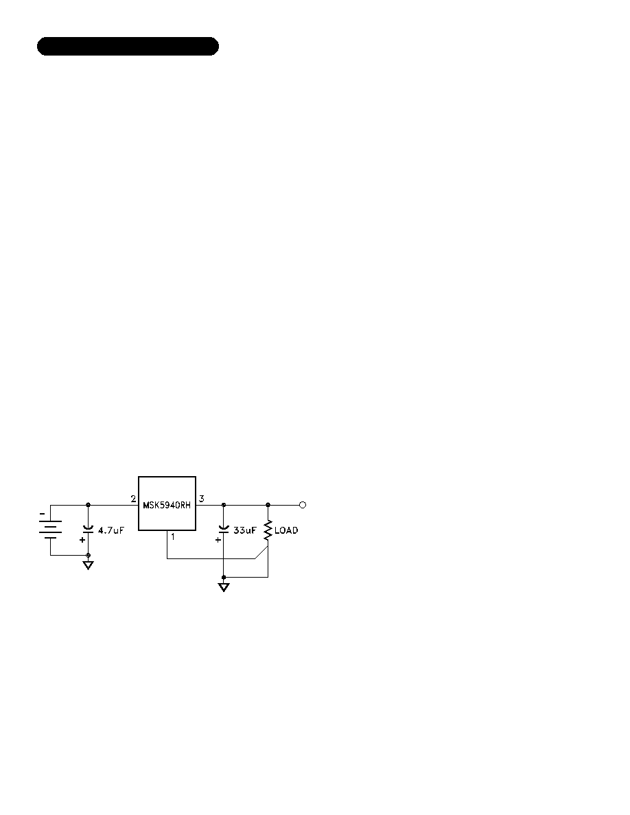
LOAD REGULATION
For best results the ground pin should be connected directly
to the load as shown below, this effectively reduces the ground
loop effect and eliminates excessive voltage drop in the sense
leg. It is also important to keep the output connection between
the regulator and the load as short as possible since this directly
affects the load regulation. For example, if 20 gauge wire were
used which has a resistance of about .008 ohms per foot, this
would result in a drop of 8mV/ft at 1Amp of load current. It is
also important to follow the capacitor selection guidelines to
achieve best performance. Refer to Figure 1 for connection dia-
gram.
BYPASS CAPACITORS
For most applications a 33uF minimum, low ESR (0.5-2 ohm)
tantalum capacitor should be attached as close to the regulator's
output as possible. This will effectively lower the regulator's
output impedance, increase transient response and eliminate any
oscillations that are normally associated with low dropout regu-
lators. Additional bypass capacitors can be used at the remote
load locations to further improve regulation. These can be either
of the tantalum or the electrolytic variety. Unless the regulator
is located very close to the power supply filter capacitor(s), a
4.7uF minimum low ESR (0.5-2 ohm) tantalum capacitor should
also be added to the regulator's input. An electrolytic may also
be substituted if desired. When substituting electrolytic in place
of tantalum capacitors, a good rule of thumb to follow is to
increase the size of the electrolytic by a factor of 10 over the
tantalum value.
Low Dropout Negative Power Supply
MSK 5940RH TYPICAL APPLICATION:
FIGURE 1
3
PRELIMINARY Rev. C 6/08
Radiation performance curves for TID testing will be gen-
erated for all radiation testing performed by MS Kennedy.
These curves will show performance trends throughout the
TID test process and will be located in the MSK 5940RH
radiation test report. The complete radiation test report will
be available in the RAD HARD PRODUCTS section on the
MSK website.
TOTAL DOSE RADIATION TEST
PERFORMANCE
相关PDF资料 |
PDF描述 |
|---|---|
| MSK5940-5.0HRHTU | 5 V FIXED NEGATIVE LDO REGULATOR, 1 V DROPOUT, SFM3 |
| MSK5940-5.0RHTS | 5 V FIXED NEGATIVE LDO REGULATOR, 1.2 V DROPOUT, SFM3 |
| MSK5940-5.0RHTU | 5 V FIXED NEGATIVE LDO REGULATOR, 1.2 V DROPOUT, SFM3 |
| MSK5940-5.2ERHG | 5.2 V FIXED NEGATIVE LDO REGULATOR, 1 V DROPOUT, PSSO3 |
| MSK5940-5.2ERHTD | 5.2 V FIXED NEGATIVE LDO REGULATOR, 1 V DROPOUT, SFM3 |
相关代理商/技术参数 |
参数描述 |
|---|---|
| MSK600 | 制造商:MSK 制造商全称:M.S. Kennedy Corporation 功能描述:WIDE BANDWIDTH HIGH VOLTAGE AMPLIFIER |
| MSK601 | 制造商:MSK 制造商全称:M.S. Kennedy Corporation 功能描述:WIDE BANDWIDTH HIGH VOLTAGE AMPLIFIER |
| MSK601B | 制造商:MSK 制造商全称:M.S. Kennedy Corporation 功能描述:WIDE BANDWIDTH HIGH VOLTAGE AMPLIFIER |
| MSK604 | 制造商:MSK 制造商全称:M.S. Kennedy Corporation 功能描述:NEGATIVE OUTPUT WIDE BANDWIDTH HIGH VOLTAGE AMPLIFIER |
| MSK604B | 制造商:MSK 制造商全称:M.S. Kennedy Corporation 功能描述:NEGATIVE OUTPUT WIDE BANDWIDTH HIGH VOLTAGE AMPLIFIER |
发布紧急采购,3分钟左右您将得到回复。