- 您现在的位置:买卖IC网 > PDF目录188956 > MXA2500GF (Electronic Theatre Controls, Inc.) Improved, Ultra Low Noise 【1.7 g Dual Axis Accelerometer with Absolute Outputs PDF资料下载
参数资料
| 型号: | MXA2500GF |
| 厂商: | Electronic Theatre Controls, Inc. |
| 英文描述: | Improved, Ultra Low Noise 【1.7 g Dual Axis Accelerometer with Absolute Outputs |
| 中文描述: | 改进的,超低噪音【一点七克双轴加速度计的绝对输出 |
| 文件页数: | 6/8页 |
| 文件大小: | 340K |
| 代理商: | MXA2500GF |
MEMSIC MXA2500G/M Rev. E
Page 6 of 8
1/19/2005
MXA2500G/M PIN DESCRIPTIONS
VDD – This is the supply input for the digital circuits and the
sensor heater in the accelerometer. The DC voltage should be
between 3.0 and 5.25 volts. Refer to the section on PCB layout
and fabrication suggestions for guidance on external parts and
connections recommended.
VDA – This is the power supply input for the analog amplifiers
in the accelerometer. Refer to the section on PCB layout and
fabrication suggestions for guidance on external parts and
connections recommended.
Gnd – This is the ground pin for the accelerometer.
AOUTX – This pin is the output of the x-axis acceleration sensor.
The user should ensure the load impedance is sufficiently high
as to not source/sink >100
A. While the sensitivity of this axis
has been programmed at the factory to be the same as the
sensitivity for the y-axis, the accelerometer can be programmed
for non-equal sensitivities on the x- and y-axes. Contact the
factory for additional information on this feature.
AOUTY – This pin is the output of the y-axis acceleration sensor.
The user should ensure the load impedance is sufficiently high
as to not source/sink >100
A. While the sensitivity of this axis
has been programmed at the factory to be the same as the
sensitivity for the x-axis, the accelerometer can be programmed
for non-equal sensitivities on the x- and y-axes. Contact the
factory for additional information on this feature.
TOUT – This pin is the buffered output of the temperature
sensor. The analog voltage at TOUT is an indication of the die
temperature. This voltage is useful as a differential
measurement of temperature from ambient and not as an
absolute measurement of temperature
Sck – The standard product is delivered with an internal clock
option (800kHz). This pin should be grounded when
operating with the internal clock. An external clock option
can be special ordered from the factory allowing the user to
input a clock signal between 400kHz and 1.6MHz.
Vref – A reference voltage is available from this pin. It is set at
2.50V typical and has 100
A of drive capability.
DISCUSSION OF TILT APPLICATIONS AND
RESOLUTION
Tilt Applications: One of the most popular applications of the
MEMSIC accelerometer product line is in tilt/inclination
measurement. An accelerometer uses the force of gravity as an
input to determine the inclination angle of an object.
A MEMSIC accelerometer is most sensitive to changes in
position, or tilt, when the accelerometer’s sensitive axis is
perpendicular to the force of gravity, or parallel to the Earth’s
surface. Similarly, when the accelerometer’s axis is parallel to
the force of gravity (perpendicular to the Earth’s surface), it is
least sensitive to changes in tilt.
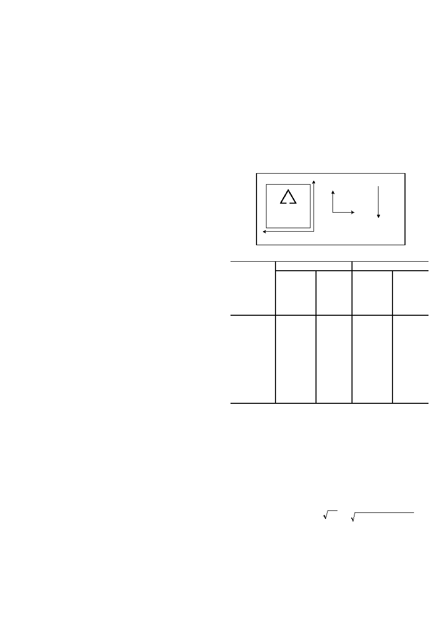
Table 1 and Figure 2 help illustrate the output changes in the
X- and Y-axes as the unit is tilted from +90
° to 0°. Notice that
when one axis has a small change in output per degree of tilt
(in mg), the second axis has a large change in output per
degree of tilt. The complementary nature of these two signals
permits low cost accurate tilt sensing to be achieved with the
MEMSIC device (reference application note AN-00MX-007).
Top View
X
Y
+900
00
gravity
ME
M
S
IC
Figure 2: Accelerometer Position Relative to Gravity
X-Axis
Y-Axis
X-Axis
Orientation
To Earth’s
Surface
(deg.)
X Output
(g)
Change
per deg.
of tilt
(mg)
Y Output
(g)
Change
per deg.
of tilt
(mg)
90
1.000
0.15
0.000
17.45
85
0.996
1.37
0.087
17.37
80
0.985
2.88
0.174
17.16
70
0.940
5.86
0.342
16.35
60
0.866
8.59
0.500
15.04
45
0.707
12.23
0.707
12.23
30
0.500
15.04
0.866
8.59
20
0.342
16.35
0.940
5.86
10
0.174
17.16
0.985
2.88
5
0.087
17.37
0.996
1.37
0
0.000
17.45
1.000
0.15
Table 1: Changes in Tilt for X- and Y-Axes
Resolution: The accelerometer resolution is limited by noise.
The output noise will vary with the measurement bandwidth.
With the reduction of the bandwidth, by applying an external
low pass filter, the output noise drops. Reduction of bandwidth
will improve the signal to noise ratio and the resolution. The
output noise scales directly with the square root of the
measurement bandwidth. The maximum amplitude of the noise,
its peak- to- peak value, approximately defines the worst case
resolution of the measurement. With a simple RC low pass
filter, the rms noise is calculated as follows:
Noise (mg rms) = Noise(mg/ Hz ) *
)
6
.
1
*
)
(
Hz
Bandwidth
The peak-to-peak noise is approximately equal to 6.6 times the
rms value (for an average uncertainty of 0.1%).
相关PDF资料 |
PDF描述 |
|---|---|
| MXA2500GL | Improved, Ultra Low Noise 【1.7 g Dual Axis Accelerometer with Absolute Outputs |
| MXA2500G | Improved, Ultra Low Noise 【1.7 g Dual Axis Accelerometer with Absolute Outputs |
| MXA2500JV | Ultra Low Cost, 【1.0 g Dual Axis Accelerometer with Absolute Outputs |
| MXA2500J | Ultra Low Cost, 【1.0 g Dual Axis Accelerometer with Absolute Outputs |
| MXA2500MF | Improved, Ultra Low Noise 【1.7 g Dual Axis Accelerometer with Absolute Outputs |
相关代理商/技术参数 |
参数描述 |
|---|---|
| MXA2500GL | 制造商:未知厂家 制造商全称:未知厂家 功能描述:Improved, Ultra Low Noise 【1.7 g Dual Axis Accelerometer with Absolute Outputs |
| MXA2500J | 制造商:未知厂家 制造商全称:未知厂家 功能描述:Ultra Low Cost, ±1.0 g Dual Axis Accelerometer with Absolute Outputs |
| MXA2500JV | 制造商:未知厂家 制造商全称:未知厂家 功能描述:Ultra Low Cost, 【1.0 g Dual Axis Accelerometer with Absolute Outputs |
| MXA2500K | 制造商:未知厂家 制造商全称:未知厂家 功能描述:Ultra Low Cost, ±1.0 g Dual Axis Accelerometer with Absolute Outputs |
| MXA2500KV | 制造商:未知厂家 制造商全称:未知厂家 功能描述:Ultra Low Cost, ±1.0 g Dual Axis Accelerometer with Absolute Outputs |
发布紧急采购,3分钟左右您将得到回复。