- 您现在的位置:买卖IC网 > PDF目录16760 > NCN1154MUTGEVB (ON Semiconductor)BOARD EVAL NCN1154MUT USB SWITCH PDF资料下载
参数资料
| 型号: | NCN1154MUTGEVB |
| 厂商: | ON Semiconductor |
| 文件页数: | 3/9页 |
| 文件大小: | 0K |
| 描述: | BOARD EVAL NCN1154MUT USB SWITCH |
| 设计资源: | NCN1154MUTGEVB Schematic NCN1154MUTGEVB Test Procedure NCN1154MUTGEVB Gerber Zip NCN1154MUTGEVB Bill of Materials |
| 标准包装: | 1 |
| 主要目的: | 接口,USB 2.0 开关 |
| 嵌入式: | 否 |
| 已用 IC / 零件: | NCN1154 |
| 已供物品: | 板 |
| 其它名称: | NCN1154MUTGEVB-ND NCN1154MUTGEVBOS |
NCN1154
http://onsemi.com
3
OPERATING CONDITIONS
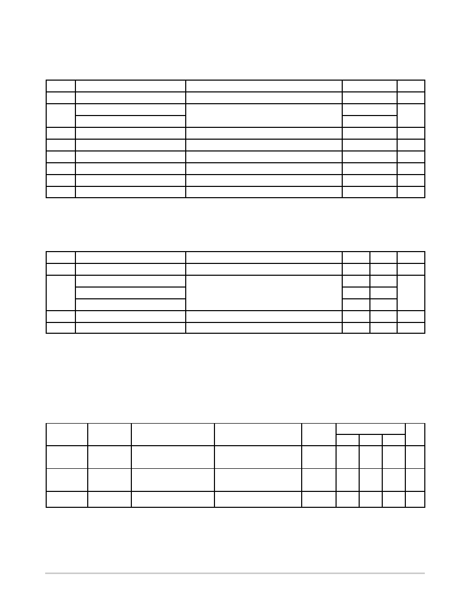
MAXIMUM RATINGS
Symbol
Pins
Parameter
Value
Unit
VCC
Positive DC Supply Voltage
0.5 to +6.0
V
VIS
R, L, D+, D, Rx, Tx
Analog I/O
2.5 to VCC + 0.5
V
COM+, COM
2.5 to +6.0
VIN
IN1, IN2
Control Input Voltage
0.5 to +6.0
V
ICC
VCC
Positive DC Supply Current
50
mA
TS
Storage Temperature
65 to +150
°C
IIS_CON
COM+, COM, R, L, D+, D, Rx, Tx
Analog Signal Continuous CurrentClosed Switch
$100
mA
IIS_PK
COM+, COM, R, L, D+, D, Rx, Tx
Analog Signal Continuous Current 10% Duty Cycle
$500
mA
IIN
IN1, IN2
Control Input Current
1.0
mA
Stresses exceeding Maximum Ratings may damage the device. Maximum Ratings are stress ratings only. Functional operation above the
Recommended Operating Conditions is not implied. Extended exposure to stresses above the Recommended Operating Conditions may affect
device reliability.
NOTE: These devices have limited builtin ESD protection. The leads should be shorted together or the device placed in conductive foam
during storage or handling to prevent electrostatic damage.
RECOMMENDED OPERATING CONDITIONS
Symbol
Pins
Parameter
Min
Max
Unit
VCC
Positive DC Supply Voltage
2.7
5.0
V
VIS
D+ to COM+, D to COM
Analog Signal Voltage (Note 1)
GND
VCC
V
L to COM+, R to COM
2.0
VCC
Tx to COM+, Rx to COM
GND
VCC
VIN
IN1, IN2
Control Input Voltage
GND
VCC
V
TA
Operating Temperature
40
+85
°C
Minimum and maximum values are guaranteed through test or design across the Recommended Operating Conditions, where applic-
able. Typical values are listed for guidance only and are based on the particular conditions listed for section, where applicable. These
conditions are valid for all values found in the characteristics tables unless otherwise specified in the test conditions.
1. In USB mode, any signal supplied to the offstate audio inputs R, L may not swing below ground or above 1.5 V.
DC ELECTRICAL CHARACTERISTICS
CONTROL INPUT Min and Max apply for TA between 40°C to +85°C and TJ up to +125°C (Unless otherwise noted). Typical values
are referenced to TA = +25°C, VCC = 3.3 V.
Symbol
Pins
Parameter
Test Conditions
VCC (V)
40
°C to +85°C
Unit
Min
Typ
Max
VIH
IN1, IN2
Control Input HIGH Voltage
2.7
3.3
4.2
1.3
1.4
1.5
V
VIL
IN1, IN2
Control Input LOW Voltage
2.7
3.3
4.2
0.4
V
IIN
IN1, IN2
Current Input Leakage
Current
0 ≤ VIS ≤ VCC
±50
nA
相关PDF资料 |
PDF描述 |
|---|---|
| H3DDH-3418G | IDC CABLE - HKR34H/AE34G/HKR34H |
| H1CXH-1636G | IDC CABLE - HKC16H/AE16G/X |
| NCS2553DGEVB | BOARD EVALUATION NCS2553D |
| H3CCS-1418G | IDC CABLE - HKC14S/AE14G/HKC14S |
| EBC26DRAI | CONN EDGECARD 52POS R/A .100 SLD |
相关代理商/技术参数 |
参数描述 |
|---|---|
| NCN1188 | 制造商:ONSEMI 制造商全称:ON Semiconductor 功能描述:3:1 High Speed USB Switch with Audio and MHL Capability |
| NCN1188MUTAG | 功能描述:电源开关 IC - USB NCN1188 SIF SWITCH RoHS:否 制造商:Micrel 电源电压-最小:2.7 V 电源电压-最大:5.5 V 最大工作温度:+ 85 C 最小工作温度:- 40 C 封装 / 箱体:SOIC-8 封装:Tube |
| NCN15-30GM40-N0 | 制造商:PEPPERL+FUCHS 功能描述:Sensor, Proximity, Inductive, NAMUR |
| NCN15-30GM40-N0 10M | 制造商:PEPPERL+FUCHS 功能描述:Inductive NAMUR |
| NCN15-30GM40-N0-10M | 制造商:PEPPERL+FUCHS 功能描述:Sensor, Proximity, Inductive, NAMUR |
发布紧急采购,3分钟左右您将得到回复。