参数资料
| 型号: | NCP1605LCDTVGEVB |
| 厂商: | ON Semiconductor |
| 文件页数: | 20/30页 |
| 文件大小: | 0K |
| 描述: | BOARD EVAL NCP1605/1396 |
| 设计资源: | NCP1605LCDTVGEVB Schematic NCP1605LCDTVGEVB Gerber Files NCP1605LCDTVGEVB Bill of Materials |
| 标准包装: | 1 |
| 系列: | * |
第1页第2页第3页第4页第5页第6页第7页第8页第9页第10页第11页第12页第13页第14页第15页第16页第17页第18页第19页当前第20页第21页第22页第23页第24页第25页第26页第27页第28页第29页第30页
�� �
�
�NCP1027�
�20-� 8.7� v� Rlimit� v� 12-� 8� ,� that� is� to� say� :� 1.8� k� W� t� R� limit�
�t� 4� k� W� .�
�Plugging� the� values� in� Equation� 3� gives� the� limits� within�
�which� R� limit� shall� be� selected:�
�6m� 1m�
�If� we� design� a� 65� kHz� power� supply� delivering� 12� V,� then�
�the� ratio� between� auxiliary� and� power� must� be:� 12/20� =� 0.6.�
�The� OVP� latch� will� activate� when� the� clamp� current�
�exceeds� 6.0� mA.� This� will� occur� when� Vauxiliary� grows� up�
�to:�
�1.� 8.7� +� 1.8� k� (6� m� +� 1.8� m)� ≈� 23� V� for� the� first�
�boundary� (� R� limit� =� 1.8� k� W� ).�
�2.� 8.7� +� 4� k� (6� m� +� 1.8� m)� ≈� 40� V� for� the� second�
�boundary� (� R� limit� =� 4.0� k� W� ).�
�Due� to� a� 0.6� ratio� between� the� auxiliary� V� CC� and� the�
�power� winding,� the� auxiliary� OVP� will� be� seen� as� a� lower�
�overshoot� on� the� real� output:�
�1.� 23� 0.6� ≈� 13.8� V�
�2.� 40� 0.6� ≈� 24� V�
�As� one� can� see,� tweaking� the� R� limit� value� will� allow� the�
�selection� of� a� given� overvoltage� output� level.� Theoretically�
�predicting� the� auxiliary� drop� from� nominal� to� standby� is� an�
�almost� impossible� exercise� since� many� parameters� are�
�involved,� including� the� converter� time� constants.� Fine�
�tuning� of� R� limit� thus� requires� a� few� iterations� and�
�experiments� on� a� breadboard� to� check� the� auxiliary� voltage�
�variations� but� also� the� output� voltage� excursion� in� fault.�
�Once� properly� adjusted,� the� fail-safe� protection� will�
�preclude� any� lethal� voltage� runaways� in� case� a� problem�
�would� occur� in� the� feedback� loop.�
�>� 30� ms�
�Figure� 35.� The� burst� frequency� becomes� so� low�
�that� it� is� difficult� to� keep� an� adequate� level� on� the�
�auxiliary� V� CC� .�
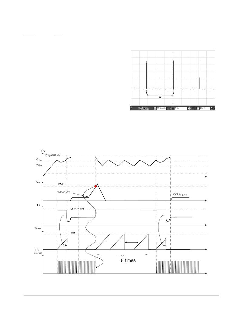
�Figure� 36� describes� the� main� signal� variations� when� the�
�part� operates� in� auto-recovery� OVP.�
�Figure� 36.� If� the� V� CC� current� exceeds� a� certain� threshold,� an� auto-recovery� protection� is�
�activated� and� protects� the� design.�
�http://onsemi.com�
�20�
�相关PDF资料 |
PDF描述 |
|---|---|
| NCP1608BOOSTGEVB | BOARD EVAL NCP1608 100W BOOST |
| NCP1631PFCGEVB | BOARD DEMO NCP1631 INTERLEAV PFC |
| NCP1650EVB | BOARD EVAL NCP1650 PFC CTLR |
| NCP1652L48VGEVB | BOARD EVAL 100W 48V NCP1652 PFC |
| NCP1653EVB | BOARD EVAL FOR NCP1653 |
相关代理商/技术参数 |
参数描述 |
|---|---|
| NCP1606ADR2G | 功能描述:功率因数校正 IC PWR FCTR CONTROLLER RoHS:否 制造商:Fairchild Semiconductor 开关频率:300 KHz 最大功率耗散: 最大工作温度:+ 125 C 安装风格:SMD/SMT 封装 / 箱体:SOIC-8 封装:Reel |
| NCP1606APG | 功能描述:功率因数校正 IC LO CST PWR FCTR CONT RoHS:否 制造商:Fairchild Semiconductor 开关频率:300 KHz 最大功率耗散: 最大工作温度:+ 125 C 安装风格:SMD/SMT 封装 / 箱体:SOIC-8 封装:Reel |
| NCP1606BDR2G | 功能描述:功率因数校正 IC PWR FCTR CONTROLLER RoHS:否 制造商:Fairchild Semiconductor 开关频率:300 KHz 最大功率耗散: 最大工作温度:+ 125 C 安装风格:SMD/SMT 封装 / 箱体:SOIC-8 封装:Reel |
| NCP1606BOOSTGEVB | 功能描述:电源管理IC开发工具 OSPI NCP1606 100 W BOOST RoHS:否 制造商:Maxim Integrated 产品:Evaluation Kits 类型:Battery Management 工具用于评估:MAX17710GB 输入电压: 输出电压:1.8 V |
| NCP1606BPG | 功能描述:功率因数校正 IC LO CST PWR FCTR CONT RoHS:否 制造商:Fairchild Semiconductor 开关频率:300 KHz 最大功率耗散: 最大工作温度:+ 125 C 安装风格:SMD/SMT 封装 / 箱体:SOIC-8 封装:Reel |
发布紧急采购,3分钟左右您将得到回复。