- 您现在的位置:买卖IC网 > PDF目录20307 > NCP1653DR2G (ON Semiconductor)IC PFC CONTROLLER CCM 8SOIC PDF资料下载
参数资料
| 型号: | NCP1653DR2G |
| 厂商: | ON Semiconductor |
| 文件页数: | 11/19页 |
| 文件大小: | 0K |
| 描述: | IC PFC CONTROLLER CCM 8SOIC |
| 标准包装: | 1 |
| 模式: | 连续导电(CCM) |
| 频率 - 开关: | 90kHz ~ 110kHz |
| 电源电压: | 8.75 V ~ 18 V |
| 工作温度: | -40°C ~ 125°C |
| 安装类型: | 表面贴装 |
| 封装/外壳: | 8-SOIC(0.154",3.90mm 宽) |
| 供应商设备封装: | 8-SOICN |
| 包装: | 标准包装 |
| 其它名称: | NCP1653DR2GOSDKR |
�� �
�
�NCP1653,� NCP1653A�
�2� Vac� *� 4� V� Vac�
�Ivac� +�
�[�
�IS� +�
�IL�
�Pin� +� ac� +�
�Vout�
�Vcontrol�
�96%� I� ref� ref� I� FB�
�R1�
�Pout� +� h� Pin� +� h�
�Vout�
�stands� for� the� RMS.� I� vac� is� a� constant� in� the� 50� or� 60� Hz�
�bandwidth.� Multiplier� resistor� R� M� is� the� external� resistor�
�connected� to� the� multiplier� voltage� V� M� pin� (Pin� 5).� It� is� also�
�constant.� R� M� directly� limits� the� maximum� input� power�
�capability� and� hence� its� value� affects� the� NCP1653� to�
�operate� in� either� “follower� boost� mode”� or� “� constant�
�output� voltage� mode”.�
�(eq.9)�
�Rvac� )� 12� k� W� R� vac�
�Sense� current� I� S� is� proportional� to� the� inductor� current� I� L�
�as� described� in� (eq.10).� I� L� consists� of� the� high� ?� frequency�
�component� (which� depends� on� di/dt� or� inductor� L)� and�
�low� ?� frequency� component� (which� is� I� L� ?� 50� ).�
�RCS� (eq.10)�
�RS�
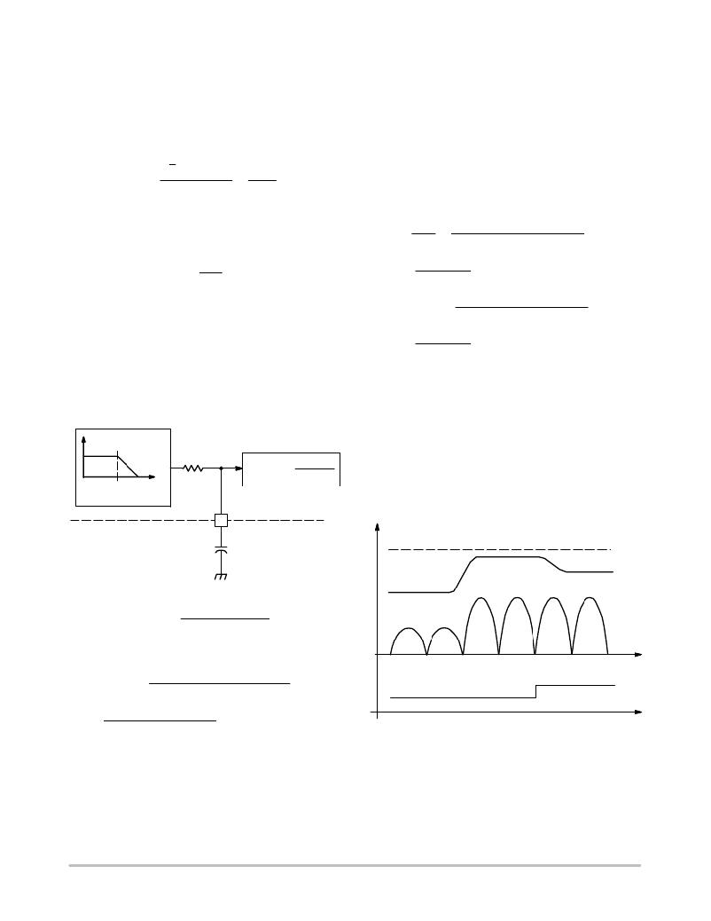
�Control� current� I� control� is� a� roughly� constant� current� that�
�comes� from� the� PFC� output� voltage� V� out� that� is� a� slowly�
�varying� signal.� The� bandwidth� of� I� control� can� be�
�additionally� limited� by� inserting� an� external� capacitor�
�C� control� to� the� control� voltage� V� control� pin� (Pin� 2)� in�
�Figure� 30.� It� is� recommended� to� limit� f� control� ,� that� is� the�
�bandwidth� of� V� control� (or� I� control� ),� below� 20� Hz� typically� to�
�achieve� power� factor� correction� purpose.� Typical� value� of�
�C� control� is� between� 0.1� m� F� and� 0.33� m� F.�
�V� reg�
�300� k�
�I� control� =�
�I�
�Regulation� Block�
�over� the� bandwidth� of� 50� or� 60� Hz� and� power� factor� is�
�corrected.�
�Practically,� the� differential� ?� mode� inductance� in� the�
�front� ?� ended� EMI� filter� improves� the� filtering� performance�
�of� capacitor� C� filter� .� Therefore,� the� multiplier� capacitor� C� M�
�is� generally� with� a� larger� value� comparing� to� the� filter�
�capacitor� C� filter� .�
�Input� and� output� power� (P� in� and� P� out� )� are� derived� in�
�(eq.13)� when� the� circuit� efficiency� η� is� obtained� or�
�assumed.� The� variable� V� ac� stands� for� the� RMS� input�
�voltage.�
�V 2 2 RS R vac Icontrol Vref Vac�
�Zin� RM� RCS� Vout�
�(eq.13a)�
�Icontrol Vac�
�T�
�2 RS R vac Icontrol Vref Vac�
�RM� RCS� Vout�
�(eq.13b)�
�Icontrol Vac�
�T�
�Follower� Boost�
�The� NCP1653� operates� in� follower� boost� mode� when�
�I� control� is� constant.� If� I� control� is� constant� based� on� (eq.13),� for�
�a� constant� load� or� power� demand� the� output� voltage� V� out� of�
�the� converter� is� proportional� to� the� RMS� input� voltage� V� ac� .� It�
�means� the� output� voltage� V� out� becomes� lower� when� the� RMS�
�input� voltage� V� ac� becomes� lower.� On� the� other� hand,� the�
�output� voltage� V� out� becomes� lower� when� the� load� or� power�
�demand� becomes� higher.� It� is� illustrated� in� Figure� 31.�
�Vcontrol�
�2�
�Ccontrol�
�V� out� (Traditional� boost)�
�Figure� 30.� V� control� Low� ?� Pass� Filtering�
�V� out� (Follower� boost)�
�Ccontrol� u�
�1�
�2� p� 300� k� W� fcontrol�
�(eq.11)�
�V� in�
�From� (eq.7)� ?� (eq.10),� the� input� impedance� Z� in� is�
�re� ?� formulated� in� (eq.12).�
�time�
�Zin� +�
�RM� RCS� Vac� Vout� IL�
�2� RS� R� vac� Icontrol� Vref� IL� ?� 50�
�P� out�
�Zin� +�
�RM� RCS� Vac� Vout�
�2� RS� R� vac� Icontrol� Vref�
�whenIL� +� IL� ?� 50�
�(eq.12)�
�Figure� 31.� Follower� Boost� Characteristics�
�time�
�The� multiplier� capacitor� C� M� is� the� one� to� filter� the�
�high� ?� frequency� component� of� the� multiplier� voltage� V� M� .�
�The� high� ?� frequency� component� is� basically� coming� from�
�the� inductor� current� I� L� .� On� the� other� hand,� the� filter�
�capacitor� C� filter� similarly� removes� the� high� ?� frequency�
�component� of� inductor� current� I� L� .� If� the� capacitors� C� M� and�
�C� filter� match� with� each� other� in� terms� of� filtering� capability,�
�I� L� becomes� I� L� ?� 50� .� Input� impedance� Z� in� is� roughly� constant�
�Follower� Boost� Benefits�
�The� follower� boost� circuit� offers� an� opportunity� to� reduce�
�the� output� voltage� V� out� whenever� the� RMS� input� voltage�
�V� ac� is� lower� or� the� power� demand� P� out� is� higher.� Because�
�of� the� step� ?� up� characteristics� of� boost� converter,� the� output�
�voltage� V� out� will� always� be� higher� than� the� input� voltage�
�V� in� even� though� V� out� is� reduced� in� follower� boost� operation.�
�http://onsemi.com�
�11�
�相关PDF资料 |
PDF描述 |
|---|---|
| F221K25Y5RN63J5R | CAP CER 220PF 1KV 10% RADIAL |
| F151K25Y5RN6UJ5R | CAP CER 150PF 1KV 10% RADIAL |
| R0.25S-1515/HP | CONV DC/DC 0.25W 15V IN 15V OUT |
| F101K25Y5RN6UJ5R | CAP CER 100PF 1KV 10% RADIAL |
| TAJA336M006RNJ | CAP TANT 33UF 6.3V 20% 1206 |
相关代理商/技术参数 |
参数描述 |
|---|---|
| NCP1653EVB | 功能描述:BOARD EVAL FOR NCP1653 RoHS:是 类别:编程器,开发系统 >> 评估演示板和套件 系列:- 标准包装:1 系列:PCI Express® (PCIe) 主要目的:接口,收发器,PCI Express 嵌入式:- 已用 IC / 零件:DS80PCI800 主要属性:- 次要属性:- 已供物品:板 |
| NCP1653GEVB | 制造商:ON Semiconductor 功能描述:NCP1653 PFC CCM STEP-UP - Bulk 制造商:ON Semiconductor 功能描述:BOARD EVAL FOR NCP1653 |
| NCP1653P | 功能描述:功率因数校正 IC Fixed Frequency RoHS:否 制造商:Fairchild Semiconductor 开关频率:300 KHz 最大功率耗散: 最大工作温度:+ 125 C 安装风格:SMD/SMT 封装 / 箱体:SOIC-8 封装:Reel |
| NCP1653PG | 功能描述:功率因数校正 IC Fixed Frequency Current Mode PFC RoHS:否 制造商:Fairchild Semiconductor 开关频率:300 KHz 最大功率耗散: 最大工作温度:+ 125 C 安装风格:SMD/SMT 封装 / 箱体:SOIC-8 封装:Reel |
| NCP1654BD133R2G | 功能描述:功率因数校正 IC NCP1654 - 133KHZ RoHS:否 制造商:Fairchild Semiconductor 开关频率:300 KHz 最大功率耗散: 最大工作温度:+ 125 C 安装风格:SMD/SMT 封装 / 箱体:SOIC-8 封装:Reel |
发布紧急采购,3分钟左右您将得到回复。