- 您现在的位置:买卖IC网 > Datasheet目录45 > NIS5132MN3TXG (ON Semiconductor)IC ELECTRONIC FUSE 12V 10-DFN Datasheet资料下载
参数资料
| 型号: | NIS5132MN3TXG |
| 厂商: | ON Semiconductor |
| 文件页数: | 8/11页 |
| 文件大小: | 258K |
| 描述: | IC ELECTRONIC FUSE 12V 10-DFN |
| 标准包装: | 3,000 |
| 功能: | 电子保险丝 |
| 输入电压: | 9 V ~ 18 V |
| 电流 - 输出: | 3.6A |
| 工作温度: | -40°C ~ 150°C |
| 安装类型: | 表面贴装 |
| 封装/外壳: | 10-VFDFN 裸露焊盘 |
| 供应商设备封装: | 10-DFN(3x3) |
| 包装: | 带卷 (TR) |
NIS5132 Series
http://onsemi.com
8
40
45
50
55
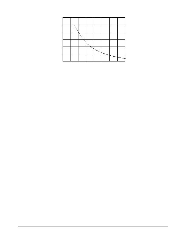
7.0
9.0
11
13
15
V
CC
(V)
Figure 18. On Resistance vs. V
CC
APPLICATION INFORMATION
Basic Operation
This device is a selfprotected, resettable, electronic fuse.
It contains circuits to monitor the input voltage, output
voltage, output current and die temperature.
On application of the input voltage, the device will apply
the input voltage to the load based on the restrictions of the
controlling circuits. The dv/dt of the output voltage will be
controlled by the internal dv/dt circuit. The output voltage
will slew from 0 V to the rated output voltage in 2 ms, unless
additional capacitance is added to the dv/dt pin.
The device will remain on as long as the temperature does
not exceed the 175癈 limit that is programmed into the chip.
The current limit circuit does not shut down the part but will
reduce the conductivity of the FET to maintain a constant
current at the internally set current limit level. The input
overvoltage clamp also does not shutdown the part, but will
limit the output voltage to 15 V in the event that the input
exceeds that level.
An internal charge pump provides bias for the gate voltage
of the internal nchannel power FET and also for the current
limit circuit. The remainder of the control circuitry operates
between the input voltage (V
CC
) and ground.
Current Limit
The current limit circuit uses a SENSEFET along with a
reference and amplifier to control the peak current in the
device. The SENSEFET allows for a small fraction of the
load current to be measured, which has the advantage of
reducing the losses in the sense resistor as well as increasing
the value and decreasing the power rating of the sense
resistor. Sense resistors are typically in the tens of ohms
range with power ratings of several milliwatts making them
very inexpensive chip resistors.
The current limit circuit has two limiting values, one for
overload events which are defined as the mode of operation
in which the gate is high and the FET is fully enhanced. The
short circuit mode of operation occurs when the device is
actively limiting the current and the gate is at an intermediate
level. For a more detailed description of this circuit please
refer to application note AND8140.
There are two methods of biasing the current limit circuit
for this device. They are shown in the two application
figures. Direct current sensing connects the sense resistor
between the current limit pin and the load. This method
includes the bond wire resistance in the current limit circuit.
This resistance has an impact on the current limit levels for
a given resistor and may vary slightly depending on the
impedance between the sense resistor and the source pins.
The on resistance of the device will be slightly lower in this
configuration since all five source pins are connected in
parallel and therefore, the effective bond wire resistance is
one fifth of the resistance for any given pin.
The other method is Kelvin sensing. This method uses one
of the source pins as the connection for the current sense
resistor. This connection senses the voltage on the die and
therefore any bond wire resistance and external impedance
on the board have no effect on the current limit levels. In this
configuration the on resistance is slightly increased relative
to the direct sense method since only for of the source pins
are used for power.
Overvoltage Clamp (MN1 & MN2 Versions)
The overvoltage clamp consists of an amplifier and
reference. It monitors the output voltage and if the input
voltage exceeds 15 V, the gate drive of the main FET is
reduced to limit the output. This is intended to allow
operation through transients while protecting the load. If an
overvoltage condition exists for many seconds, the device
may overheat due to the voltage drop across the FET
combined with the load current. In this event, the thermal
protection circuit would shut down the device.
相关PDF资料 |
PDF描述 |
|---|---|
| NSI45015WT1G | IC LED DRIVER LINEAR SOD-123 |
| NSI45020AT1G | IC LED DRIVER LINEAR SOD-123 |
| NSI45020JZT1G | IC LED DRVR CONST CURRENT SOT223 |
| NSI45020T1G | IC CCR/LED DVR 45V 20MA SOD-123 |
| NSI45025AT1G | IC LED DRIVER LINEAR SOD-123 |
相关代理商/技术参数 |
参数描述 |
|---|---|
| NIS5135 | 制造商:ONSEMI 制造商全称:ON Semiconductor 功能描述:+5 Volt Electronic Fuse |
| NIS5135MN1TXG | 功能描述:热插拔功率分布 5.0V Electronic Fuse RoHS:否 制造商:Texas Instruments 产品:Controllers & Switches 电流限制: 电源电压-最大:7 V 电源电压-最小:- 0.3 V 工作温度范围: 功率耗散: 安装风格:SMD/SMT 封装 / 箱体:MSOP-8 封装:Tube |
| NIS5135MN2TXG | 功能描述:热插拔功率分布 5.0V Electronic Fuse RoHS:否 制造商:Texas Instruments 产品:Controllers & Switches 电流限制: 电源电压-最大:7 V 电源电压-最小:- 0.3 V 工作温度范围: 功率耗散: 安装风格:SMD/SMT 封装 / 箱体:MSOP-8 封装:Tube |
| NIS5232MN1TXG | 制造商:ON Semiconductor 功能描述:Electronic Fuse 10-Pin DFN EP T/R 制造商:ON Semiconductor 功能描述:NIS5232MN1TXG 8A E-FUSE L - Tape and Reel |
| NIS6111 | 制造商:ON Semiconductor 功能描述:IC DIODE OR-ING 30A 24V PLLP32 |
发布紧急采购,3分钟左右您将得到回复。