- 您现在的位置:买卖IC网 > PDF目录189253 > NQ20W20EGV10NRS-G (SYNQOR INC) 2-OUTPUT 200 W DC-DC REG PWR SUPPLY MODULE PDF资料下载
参数资料
| 型号: | NQ20W20EGV10NRS-G |
| 厂商: | SYNQOR INC |
| 元件分类: | 电源模块 |
| 英文描述: | 2-OUTPUT 200 W DC-DC REG PWR SUPPLY MODULE |
| 封装: | ROHS COMPLIANT, EIGHT BRICK PACKAGE-8 |
| 文件页数: | 9/10页 |
| 文件大小: | 855K |
| 代理商: | NQ20W20EGV10NRS-G |
Product # NQ20x20EGx10
Phone 1-888-567-9596
www.synqor.com
Doc.# 005-0005379 Rev. B
09/18/09
Page 8
Input:
Outputs:
Current:
Package:
9 - 20V
0 - 20V
10A
Eighth-brick
Technical Specification
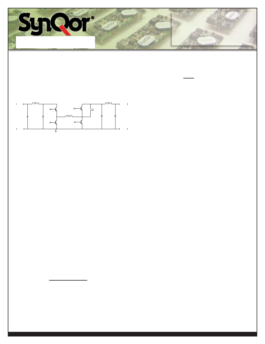
BASICOPERATIONANDFEATURES
Theseconvertersuseadigitalcontrollerforthebuckstageand
booststage(seeFigureA).Itautomaticallychangesoperating
mode(buckmodeorboost)whenthelinevoltageoroutputset
pointchanges.Bothstagesareaccomplishedwithsynchronous
rectifiers. Very high efficiency is maintained over wide input
and output ranges by shifting operational modes and use of
synchronousrectifiers.
Vin+
Vin-
Linput
Cin1
Cin2
GATE_Q1
GATE_Q3
GATE_Q4
GATE_Q2
Q1
Q3
Q4
Q2
L
Loutput
JUMPER
Cout1
Cout2
Vout+
Vout-
Figure A: Topology
Wmode:Q3,Q4arepopulated,Jumperisopen.
Tmode:Q3,Q4areopen,Jumperispopulated.
The converter runs at a fixed frequency with a predictable
EMIperformance.
Thisseriesofquarter-brickandeighth-brickconvertersusethe
industrystandardfootprintandpin-outconfiguration.
CONTROLFEATURES
REMOTE ON/OFF:TheON/OFFinputpermitstheusertocon-
trolwhentheconverterisonoroff.OnlyNegativeON/OFFlogic
isavailableinthispowermoduleseries.
NegativelogicON/OFFsignalturnsthemoduleOFFduringlogic
high(leavethepinfloatingorsetvoltagebetween1.8~3.3V)and
turnsthemoduleONduringlogiclow[tietoVin(-)].
OUTPUT VOLTAGE TRIM: The output voltage can be
programmed to any voltage between 0 V dc and Vmax by
connectingoneresistorbetweenthePin6(TRIM)pinandPin5
[Sense(-)].Foradesiredoutputvoltage,thevalueoftheresistor
shouldbe:
Rtrim-up(Vout)=
[( 11830xVmax )_10912]()
Vout+0.058xVmax
Alternatively,theTRIMpincanbedrivenfromanexternal
voltagesource:
V(pin6)=2.366–2.314
(Vout)
Vmax
where:
Vout=desiredoutputvoltage
V
max
=maximumratedoutputvoltage
Tomaintaintheaccuracyoftheoutputvoltageoverloadcurrent,
itisvitalthatanytrim-upresistorbeterminateddirectlytothe
converter’sSense(-)pin(Soption)orVout(-)pin(Coption),not
attheconnectiontotheload.AseparateKelvinconnectiontothe
PCBpadfortheVout(-)isoptimal.
PROTECTIONFEATURES
Input Under-Voltage Lockout: The converter is designed
toturnoffwhentheinputvoltageistoolow,helpingavoidan
inputsysteminstabilityproblem,describedinmoredetailinthe
application note titled “Input System Instability”. The lockout
circuitry is a comparator with DC hysteresis. When the input
voltage is rising, it must exceed the typical Turn-On Voltage
Threshold value (listed on the specification page) before the
converter will turn on. Once the converter is on, the input
voltagemustfallbelowthetypicalTurn-OffVoltageThreshold
valuebeforetheconverterwillturnoff.
Output Current Shutdown: To provide protection in an
outputshortcondition,theunitisequippedwithinternalshort
circuit protection. When the short protection is triggered, the
unitshutdownsfirst.Afterapproximately16msinhibittime,the
unitsturnonagain.Iftheshortconditionremains,thecurrent
limit circuit will limit the output current. The units operate
normallyoncethefaultconditionisremoved.
Internal Over-Voltage Protection: To fully protect from
excessive output voltage, the output over-voltage shutdown
circuitryiscontained.ThisOVPisindependentofthetrimmedset
point.Theshutdownpointisfixedonthestandardoption.
Over-Temperature Shutdown: A temperature sensor on
the converter senses the average temperature of the module.
The thermal shutdown circuit is designed to turn the converter
off when the temperature at the sensed location reaches the
Over-Temperature Shutdown value. It will allow the converter
to turn on again when the temperature of the sensed location
fallsbytheamountoftheOver-TemperatureShutdownRestart
Hysteresisvalue.
12465
.0569
2.180
Application Section
相关PDF资料 |
PDF描述 |
|---|---|
| NR-18-3.575611MHZ-CL | QUARTZ CRYSTAL RESONATOR, 3.575611 MHz |
| NRG4026T6R6M | 1 ELEMENT, 6.6 uH, FERRITE-CORE, GENERAL PURPOSE INDUCTOR, SMD |
| NRH3012T6R8M | 1 ELEMENT, 6.8 uH, FERRITE-CORE, GENERAL PURPOSE INDUCTOR, SMD |
| NRH3012T4R7M | 1 ELEMENT, 4.7 uH, FERRITE-CORE, GENERAL PURPOSE INDUCTOR, SMD |
| NRH3012T1R0N | 1 ELEMENT, 1 uH, FERRITE-CORE, GENERAL PURPOSE INDUCTOR, SMD |
相关代理商/技术参数 |
参数描述 |
|---|---|
| NQ20W20ETC20NKC-G | 制造商:SYNQOR 制造商全称:SYNQOR 功能描述:Eighth-brick DC-DC Converter |
| NQ20W20ETC20NKS-G | 制造商:SYNQOR 制造商全称:SYNQOR 功能描述:Eighth-brick DC-DC Converter |
| NQ20W20ETC20NNC-G | 制造商:SYNQOR 制造商全称:SYNQOR 功能描述:Eighth-brick DC-DC Converter |
| NQ20W20ETC20NNS-G | 制造商:SYNQOR 制造商全称:SYNQOR 功能描述:Eighth-brick DC-DC Converter |
| NQ20W20ETC20NRC-G | 制造商:SYNQOR 制造商全称:SYNQOR 功能描述:Eighth-brick DC-DC Converter |
发布紧急采购,3分钟左右您将得到回复。