- 您现在的位置:买卖IC网 > PDF目录189274 > NTHC8NB-FREQ1 (PERICOM SEMICONDUCTOR CORP) CRYSTAL OSCILLATOR, CLOCK, 24 MHz - 50 MHz, CMOS OUTPUT PDF资料下载
参数资料
| 型号: | NTHC8NB-FREQ1 |
| 厂商: | PERICOM SEMICONDUCTOR CORP |
| 元件分类: | XO, clock |
| 英文描述: | CRYSTAL OSCILLATOR, CLOCK, 24 MHz - 50 MHz, CMOS OUTPUT |
| 文件页数: | 2/2页 |
| 文件大小: | 74K |
| 代理商: | NTHC8NB-FREQ1 |
DS-104
REV D
3.8
SaRonix
NTH / NCH Series
SaRonix
Crystal Clock Oscillator
Technical Data
HCMOS
141 Jefferson Drive Menlo Park, CA 94025 USA 650-470-7700 800-227-8974 Fax 650-462-9894
All specifications are subject to change without notice.
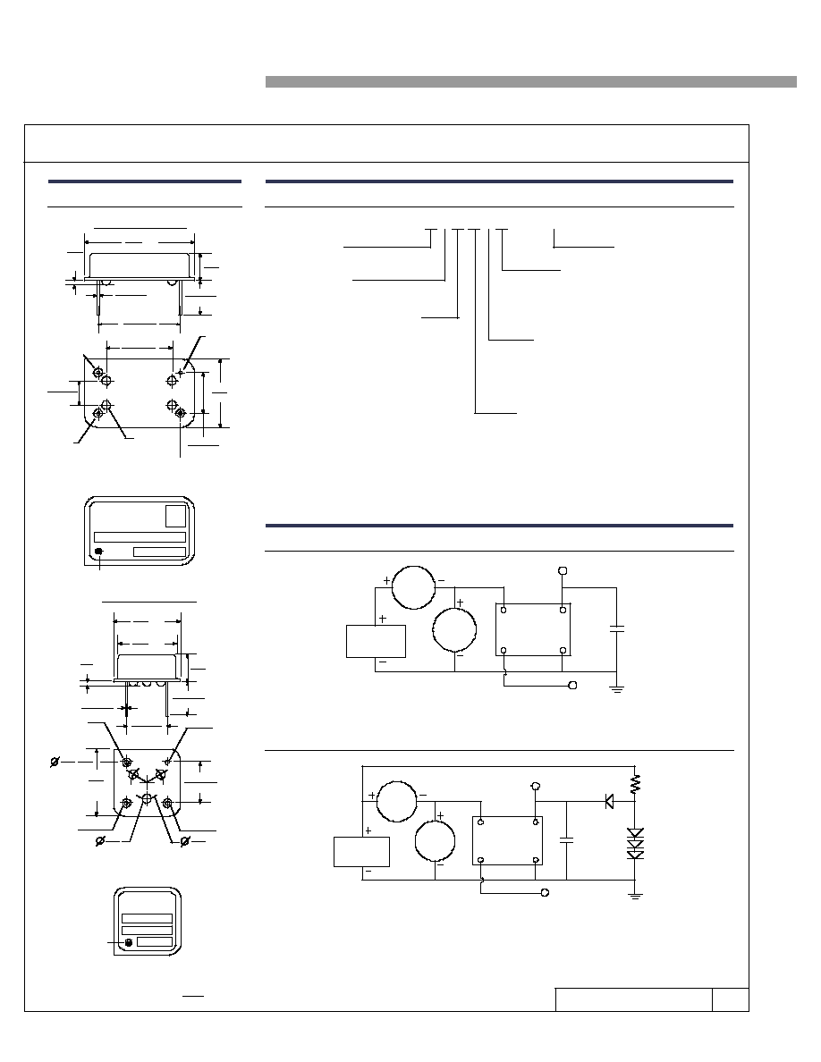
Package Details
Part Numbering Guide
20.6
.810
max
5.08
.200
max
.46±.08
.018±.003
15.24±.13
.600±.005
12.19±.13
.480±.005
4.57±.13
.180±.005
13.0
.510
(4) Glass
Insulators
Pin 7
GND
Pin 8 Output
HALF SIZE PACKAGE
max
0.9
.036
FULL SIZE PACKAGE
Pin 1
Tri-State - NTH
N/C - NCH
max
Pin 14
+5VDC
7.62±.13
.300±.005
120°
Pin 1
Tri-State - NTH
N/C - NCH
1.5
.059
13.0
.510
max
Pin 4
GND
1.5
.059
Pin 8
+5VDC
6.0
.236
Pin 5
Output
7.62±.20
.300±.008
7.62±.20
.300±.008
5.08
.200
max
.46±.051
.018±.002
0.9
.036
max
10.87
.428
max
13.0
.510
max
SARONIX
Marking Format
**
Includes Date Code, Frequency & Model
Denotes Pin 1
6.35±.51
.250±.020
6.35±.51
.250±.020
Scale: None (Dimensions in
)
mm
inches
Denotes Pin 1
** Exact locations of items may vary
Marking Format
**
Includes Date Code, Frequency & Model
Test Circuits
mA
M
POWER
SUPPLY
V M
OSCILLATOR
Pin 14 (8)
TEST
POINT
Pin 8 (5)
VCC
OUT
GND
Pin 7 (4)
Pin 1 (1)
*
TRI-STATE INPUT (NTH only)
NOTE A: CL includes probe and fixture capacitance
*( ) Indicates pin numbers for half-size package
HCMOS (Used at SaRonix)
CL = 50pF to 50 MHz
30pF above 50 MHz
(Note A)
Pin 14 (8)
V M
TEST
POINT
VCC
OUT
OSCILLATOR
Pin 8 (5)
GND
Pin 7 (4)
Pin 1 (1)
*
POWER
SUPPLY
mA
M
CL = 15pF
(Note A)
RL= 390
MMBD7000
or Equiv
TRI-STATE INPUT (NTH only)
NOTE A: CL includes probe and fixture capacitance
*( ) Indicates pin numbers for half-size package
TTL (Optional load)
T = Tri-State
C = Pin 1 N/C
Frequency
Series
H = CMOS compatible
N
H
9
– XX.XXXX
Symmetry / Temperature Range
0 = 40/60%, 0 to +70°C
2 = 40/60%, -40 to +85°C
4 = 45/55%, -40 to +85°C, TTL
0.5 to 40 MHz only
6 = 45/55%, 0 to +70°C, TTL
0.5 to 50 MHz only
A = 45/55%, 0 to +70°C, CMOS
0.5 to 70 MHz only
C = 45/55%, -40 to +85°C, CMOS
0.5 to 50 MHz only
Frequency Range
3 = 0.5 to 6 MHz
6 = 6+ to24 MHz
8 = 24+ to 100 MHz
Stability Tolerance
AA = ±(10+10) ppm* (0 to 70°C only)
A = ±25 ppm (0 to 70°C only)
B = ±50 ppm
C = ±100 ppm
Package
0 = Full Size, Thru Hole
9 = Half Size, Thru Hole
**J = Half Size, Gull Wing
**N = Half Size, Gull Wing, Spanked Leads
* ±10 ppm over operating temperature range plus ±10 ppm over all other conditions
** 80 MHz max
Example PN: NTH080C - 32.0000
相关PDF资料 |
PDF描述 |
|---|---|
| NTP133SH002 | 33 CONTACT(S), FEMALE, COMBINATION LINE CONNECTOR, RECEPTACLE |
| NTP138PH011 | 38 CONTACT(S), MALE, COMBINATION LINE CONNECTOR, PLUG |
| NTP138PH013 | 38 CONTACT(S), MALE, COMBINATION LINE CONNECTOR, PLUG |
| NTP138PH016 | 38 CONTACT(S), MALE, COMBINATION LINE CONNECTOR, PLUG |
| NTP138PH017 | 38 CONTACT(S), MALE, COMBINATION LINE CONNECTOR, PLUG |
相关代理商/技术参数 |
参数描述 |
|---|---|
| NTHC8NC3 | 制造商:未知厂家 制造商全称:未知厂家 功能描述:Crystal Clock Oscillator |
| NTHC8SA3 | 制造商:未知厂家 制造商全称:未知厂家 功能描述:Crystal Clock Oscillator |
| NTHC8SAA3 | 制造商:未知厂家 制造商全称:未知厂家 功能描述:Crystal Clock Oscillator |
| NTHC8SB3 | 制造商:未知厂家 制造商全称:未知厂家 功能描述:Crystal Clock Oscillator |
| NTHC8SC3 | 制造商:未知厂家 制造商全称:未知厂家 功能描述:Crystal Clock Oscillator |
发布紧急采购,3分钟左右您将得到回复。