- 您现在的位置:买卖IC网 > PDF目录296762 > PA33 Operational Amplifier PDF资料下载
参数资料
| 型号: | PA33 |
| 英文描述: | Operational Amplifier |
| 中文描述: | 运算放大器 |
| 文件页数: | 4/4页 |
| 文件大小: | 57K |
| 代理商: | PA33 |
OPERATING
CONSIDERATIONS
PA33 PA33A
GENERAL
Please read Application Note 1 "General Operating Consid-
erations" which covers stability, supplies, heat sinking, mount-
ing, current limit, SOA interpretation, and specification inter-
pretation. Visit www.apexmicrotech.com for design tools that
help automate tasks such as calculations for stability, internal
power dissipation, current limit; heat sink selection; Apex’s
complete Application Notes library; Technical Seminar Work-
book; and Evaluation Kits.
CURRENT LIMIT
The two current limit sense lines are to be connected directly
across the current limit sense resistor.
For the current limit to
work correctly, pin 11 must be connected to the amplifier
output side and pin 10 connected to the load side of the current
limit resistor, R
CL, as shown in Figure 1. This connection will
bypass any parasitic resistances, R
P formed by sockets and
solder joints as well as internal amplifier losses. The current
limiting resistor may not be placed anywhere in the output
circuit except where shown in Figure 1. If current limiting is not
used, pins 10 and 11 must be tied to pin 7.
The value of the current limit resistor can be calculated as
follows:
SAFE OPERATING AREA (SOA)
The MOSFET output stage of this power operational ampli-
fier has two distinct limitations:
1. The current handling capability of the MOSFET geometry
and the wire bonds.
2. The junction temperature of the output MOSFETs.
NOTE:
The output stage is protected against transient flyback.
However, for protection against sustained, high energy
flyback, external fast-recovery diodes should be used.
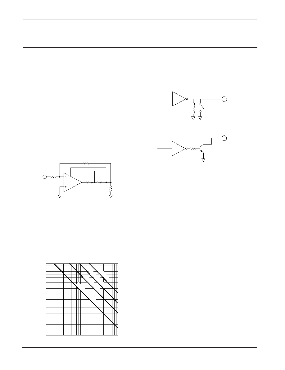
SHUTDOWN OPERATION
To disable the output stage, pin 12 is connected to ground
via relay contacts or via an electronic switch. The switching
device must be capable of sinking 2mA to complete shutdown
and capable of standing off the supply voltage +V
S. See Figure
2 for suggested circuits.
From an internal circuitry standpoint, shutdown is just a
special case of current limit where the allowed output current
is zero. As with current limit, however, a small current does flow
in the output during shutdown. A load impedance of 100 ohms
or less is required to insure the output transistors are turned off.
Note that even though the output transistors are off the output
pin is not open circuited because of the shutdown operating
current.
BOOST OPERATION
With the V
BOOST feature, the small signal stages of the
amplifier are operated at higher supply voltages than the
amplifier’s high current output stage. +V
BOOST (pin 9), and
–V
BOOST
(pin 5) are connected to the small signal circuitry of
the amplifier. +V
S (pin 8) and –VS (pin 6) are connected to the
high current output stage. An additional 5V on the V
BOOST pins
is sufficient to allow the small signal stages to drive the output
transistors into saturation and improve the output voltage
swing for extra efficient operation when required. When close
swings to the supply rails is not required the +V
BOOST and +VS
pins must be strapped together as well as the –V
BOOST and –VS
pins. The boost voltage pins must not be at a voltage lower than
the V
S pins.
COMPENSATION
The external compensation components C
C and RC are
connected to pins 3 and 4. Unity gain stability can be achieved
at any compensation capacitance greater than 470 pF with at
least 60 degrees of phase margin. At higher gains, more phase
shift can be tolerated in most designs and the compensation
capacitance can accordingly be reduced, resulting in higher
bandwidth and slew rate. Use the typical operating curves as
a guide to select C
C and RC for the application.
1
SUPPLY TO OUTPUT DIFFERENTIAL (V)
OUTPUT
CURRENT
(A)
25
10
30
100
.3
.6
.9
1.2
1.5
3
6
9
12
15
30
DC
Tc
=
125°C
DC
Tc
=
85°C
DC
Tc
=
25°C
t =
200ms
34
20
40 50
I
LIMIT = .7/RCL
Ri
1
2
10
11
RCL
PA33
RP
RL
CL
INPUT
7
R
f
FIGURE 1. CURRENT LIMIT
–LOGIC
K1
SHUTDOWN
470
Q1
FIGURE 2. SHUTDOWN OPERATION
12
SHUTDOWN
–LOGIC
A
B
This data sheet has been carefully checked and is believed to be reliable, however, no responsibility is assumed for possible inaccuracies or omissions. All specifications are subject to change without notice.
PA33U REV. A JULY 2001
2001 Apex Microtechnology Corp.
相关PDF资料 |
PDF描述 |
|---|---|
| PA33A | Operational Amplifier |
| PA35WPF | KLEMMLEISTE KABELSCHUTZ 12POL 380VAC 6A |
| PA35 | Operational Amplifier |
| PA37 | Analog IC |
| PA4-5PD11J-D01 | 9 CONTACT(S), MALE, STRAIGHT TWO PART BOARD CONNECTOR, SOLDER, PLUG |
相关代理商/技术参数 |
参数描述 |
|---|---|
| PA-33 | 制造商:CENTRALAB 功能描述: 制造商:Electro Switch Corp 功能描述: 制造商:ELECTROSWITCH 功能描述: |
| PA330 | 制造商:Distributed By MCM 功能描述:Wooden Nail Cleaning Brush |
| PA3310-N03-B | 制造商:SMC Corporation of America 功能描述:PROCESS PUMP, FLUORO, AUTO |
| PA3312 | 制造商:UTC-IC 制造商全称:UTC-IC 功能描述:DUAL 2.6W AUDIO POWER AMPLIFIER WITH FOUR SELECTABLE GAIN SETTINGS |
| PA333 | 制造商:Okaya Electric America Inc 功能描述: |
发布紧急采购,3分钟左右您将得到回复。