- 您现在的位置:买卖IC网 > PDF目录65835 > PBL3770ANS (ERICSSON POWER MODULES AB) STEPPER MOTOR CONTROLLER, 1.8 A, PDIP16 PDF资料下载
参数资料
| 型号: | PBL3770ANS |
| 厂商: | ERICSSON POWER MODULES AB |
| 元件分类: | 运动控制电子 |
| 英文描述: | STEPPER MOTOR CONTROLLER, 1.8 A, PDIP16 |
| 封装: | BATWING, PLASTIC, DIP-16 |
| 文件页数: | 7/8页 |
| 文件大小: | 140K |
| 代理商: | PBL3770ANS |
PBL 3770A
7
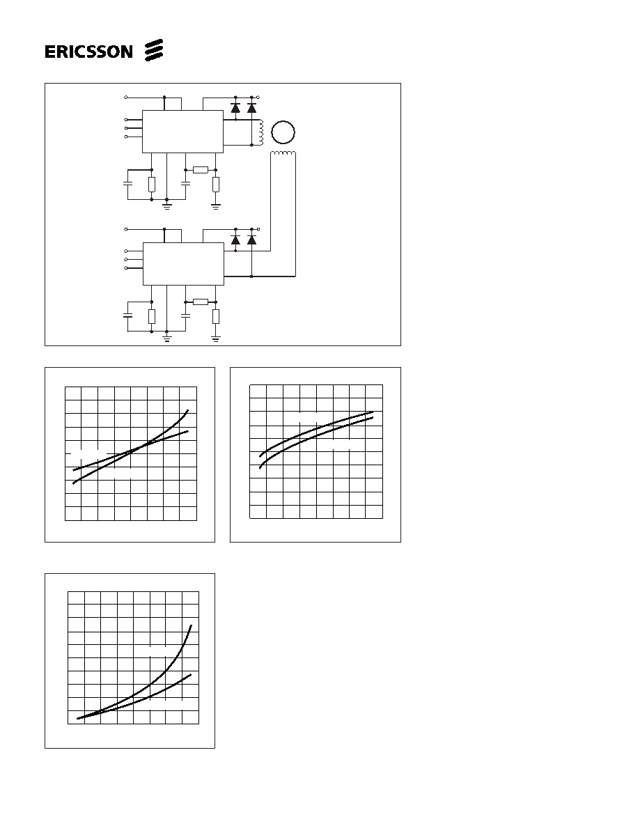
Figure 8. Typical stepper motor driver application with PBL 3770A.
Figure 9. Typical source saturation vs.
output current.
In order to minimize electromagnetic
interference, it is recommended to route
M
A and MB leads in parallel on the
printed circuit board directly to the
terminal connector. The motor wires
should be twisted in pairs, each phase
separately, when installing the motor
system.
Unused inputs
Unused inputs should be connected to
proper voltage levels in order to obtain
the highest possible noise immunity.
Ramping
A stepper motor is a synchronous motor
and does not change its speed due to
load variations. This means that the
torque of the motor must be large
enough to match the combined inertia of
the motor and load for all operation
modes. At speed changes, the requires
torque increases by the square, and the
required power by the cube of the speed
change. Ramping, i.e., controlled
acceleration or deceleration must then
be considered to avoid motor pull-out.
V
CC , VMM
The supply voltages, V
CC and VMM, can
be turned on or off in any order. Normal
dv/dt values are assumed.
Before a driver circuit board is
removed from its system, all supply
voltages must be turned off to avoid
destructive transients being generated
by the motor.
Switching frequency
The motor inductance, together with the
pulse time, t
off, determines the switching
frequency of the current regulator. The
choice of motor may then require other
values on the R
T, CT components than
those recommended in figure 6, to
obtain a switching frequency above the
audible range. Switching frequencies
above 40 kHz are not recommended
because the current regulation can be
affected.
Analog control
As the current levels can be continu-
ously controlled by modulating the V
R
input, limited microstepping can be
achieved.
VSat (V)
1.8
1.6
1.4
1.2
1.0
.8
.6
.4
.2
0
.40
.80
1.2
I M (A)
Tj = 125°C
j
T = 25
°C
1.6
VSat (V)
1.8
1.6
1.4
1.2
1.0
.8
.6
.4
.2
0
.40
.80
1.2
I M (A)
Tj = 125°C
j
T = 25
°C
1.6
Figure 10. Typical sink saturation vs.
output current.
VF (V)
1.8
1.6
1.4
1.2
1.0
.8
.6
.4
.2
0
.40
.80
1.2
I M (A)
Tj = 25 °C
j
T = 125
°C
1.6
Figure 11. Typical lower diode voltage
drop vs. recirculating current.
Interference
As the circuit operates with switched-
mode current regulation, interference-
generation problems can arise in some
applications. A good measure is then to
decouple the circuit with a 0.1
F
ceramic capacitor, located near the
package across the power line V
MM and
ground.
Also make sure that the V
Ref input is
sufficiently decoupled. An electrolytic
capacitor should be used in the +5 V rail,
close to the circuit.
The ground leads between R
S, CC and
circuit GND should be kept as short as
possible. This applies also to the leads
connecting R
S and RC to pin 16 and pin
10 respectively.
Phas
e
I
1
I
0
TC
E
M
A
M
B
V
M
V
C
V
R
GN
D
Phase
B
I
1
B
I
0
B
PBL 3770A
1
6
3,
14
8
7
9
2
1
0
1
6
4, 5
12, 13
1
5
Phase
A
I
1
A
I
0
A
1
5
Diodes are
UF 4001 or
BYV27
t
r
100
ns
Phas
e
I
1
I
0
TC
E
V
M
V
C
V
R
GN
D
M
A
M
B
PBL 3770A
1
6
3,
14
8
7
9
2
1
0
1
6
4, 5
12, 13
STEPPER
MOTOR
820
pF
820
pF
1
k
56
k
0.5
820
pF
820
pF
1
k
56
k
0.5
V
(+5
V)
C
V
(+5
V)
C
V
M
V
M
相关PDF资料 |
PDF描述 |
|---|---|
| PBL3773/1QNT | STEPPER MOTOR CONTROLLER, 0.85 A, PQCC28 |
| PBL3773/1SOT | STEPPER MOTOR CONTROLLER, 0.85 A, PDSO24 |
| PBL3773QN | STEPPER MOTOR CONTROLLER, 0.85 A, PQCC28 |
| PBL3774QNT | STEPPER MOTOR CONTROLLER, 1.2 A, PQCC28 |
| PBL3774QNS | STEPPER MOTOR CONTROLLER, 1.2 A, PQCC28 |
相关代理商/技术参数 |
参数描述 |
|---|---|
| PBL3770AQN | 制造商:未知厂家 制造商全称:未知厂家 功能描述:Stepper Motor Controller/Driver |
| PBL3770AQNS | 制造商:ERICSSON 制造商全称:Ericsson 功能描述:High Performance Stepper Motor Drive Circuit |
| PBL3770AQNT | 制造商:ERICSSON 制造商全称:Ericsson 功能描述:High Performance Stepper Motor Drive Circuit |
| PBL3770ASOS | 制造商:ERICSSON 制造商全称:Ericsson 功能描述:High Performance Stepper Motor Drive Circuit |
| PBL3770ASOT | 制造商:ERICSSON 制造商全称:Ericsson 功能描述:High Performance Stepper Motor Drive Circuit |
发布紧急采购,3分钟左右您将得到回复。