- 您现在的位置:买卖IC网 > PDF目录378041 > PBL386202QNS (ERICSSON) Subscriber Line Interface Circuit PDF资料下载
参数资料
| 型号: | PBL386202QNS |
| 厂商: | ERICSSON |
| 英文描述: | Subscriber Line Interface Circuit |
| 中文描述: | 用户线接口电路 |
| 文件页数: | 11/16页 |
| 文件大小: | 135K |
| 代理商: | PBL386202QNS |
PBL 386 20/2
11
recommended to position the 3 dB break
point of this filter between 30 and 80 Hz to
get a faster response for the dc steps that
may occur at DTMF signalling.
Capacitor C
LP
The capacitor C
, which connects between
the terminals CLP and VBAT, positions the
high end frequency break point of the low
pass filter in the dc loop in the SLIC. C
LP
together with C
and Z
(see section Two-
Wire Impedance) forms the total two wire
output impedance of the SLIC. The choise
of these programmable components have
an influence on the power supply rejection
ratio (PSRR) from VBAT to the two wire
side at sub-audio frequencies. At these
frequencies capacitor C
also influences
the transversal to longitudinal balance in
the SLIC. Table 1 suggests a suitable value
on C
. The typical value of the transversal
to longitudinal balance (T-L bal.) at 200Hz
is given in table 1 for the chosen value on
C
LP
.
T-L bal.
@ 200Hz
C
HP
[dB]
R
Feed
[
]
R
[k
]
C
LP
[nF]
[nF]
2·25
0
150
-46
47
Table 1. R
, C
and C
values for cons-
tant current feeding characteristics.
For values outside table 1, please contact
Ericsson Microelectronics for assistance.
Battery Feed
The PBL 386 20/2 SLIC emulate a battery
characteristic with current limitation
adjustable.The open loop voltage measured
between the TIPX and RINGX terminals is
tracking the battery voltage V
. The
signalling headroom, or overhead voltage
V
, is programmable with a resistor R
connected between terminal POV on the
SLIC and ground. Please refer to section
“Programmable overhead voltage(POV)”.
The battery voltage overhead,V
,depends
on the programmed signal overhead voltage
V
. V
defines the TIP to RING voltage
at open loop conditions according to
V
(at I
= 0 mA) =
|
V
|
- V
OH
.
Refer to table 2 for the typical value on
V
OH
.
SLIC
V
OH
(typ) [V]
PBL 386 20/2
2.5 +V
TRO
Table 2. Battery overhead.
The current limit (reference A - C in figure
13) is adjusted by connecting a resistor,
R
, between terminal PLC and ground
according to the equation:
1000
I
LProg
+ 4
R
LC
=
where R
LC
is in k
for I
LProg
in mA.
A second, lower battery voltage may be
connected to the device at terminal VBAT2
to reduce short loop power dissipation.
The SLIC automatically switches between
the two battery supply voltages without need
for external control. The silent battery
hybrid balance to accommodate different
line impedances without change of
hardware. In addition, the transmit and
receive gain may be adjusted. Please, refer
to the programmable CODEC/filter data
sheets for design information.
Longitudinal Impedance
A feed back loop counteracts longitudinal
voltages at the two-wire port by injecting
longitudinal currents in opposing phase.
Thus longitudinal disturbances will
appear as longitudinal currents and the
TIPX and RINGX terminals will experience
very small longitudinal voltage excursions,
leaving metallic voltages well within the
SLIC common mode range.
The SLIC longitudinal impedance per
wire, Z
and Z
, appears as typically
20
to longitudinal disturbances. It should
be noted that longitudinal currents may
exceed the dc loop current without distur-
bing the vf transmission.
Capacitors C
TC
and C
RC
The capacitors designated C
and C
RC
in figure 12, connected between TIPX
and ground as well as between RINGX
and ground, can be used for RFI filtering.
The recommended value for C
and
C
is 2200 pF. Higher capacitance
values may be used, but care must be
taken to prevent degradation of either
longitudinal balance or return loss. C
and C
contribute to a metallic imped-
ance of 1/(
π
·f·C
) = 1/(
π
·f·C
), a TIPX to
ground impedance of1/(2·
π
·f·C
TC
) and a
RINGX to ground impedance of
1/(2·
π
·f·C
RC
).
AC - DC Separation Capacitor, C
The high pass filter capacitor connected
between terminals HP and TIPX provides
the separation of the ac signal from the
dc part. C
positions the low end
frequency response break point of the ac
loop in the SLIC. Refer to table 1 for a
recommended value of C
.
Example: A C
value of 47 nF will
position the low end frequency response
3dB break point of the ac loop at 5.6 Hz
(f
) according to f
3dB
= 1/(2
π
R
HP
C
HP
)
where R
HP
= 600k
.
High-Pass Transmit Filter
The capacitor C
in figure 12 connected
between the VTX output and the
CODEC/filter forms, together with R
and/
or the input impedance of a programmable
CODEC/filter, a high-pass RC filter. It is
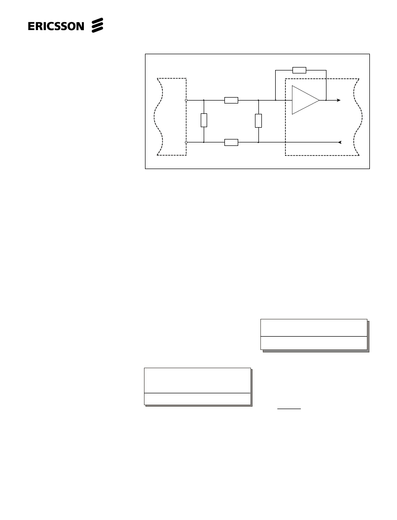
Figure 10. Hybrid function.
V
T
Combination
CODEC/Filter
R
TX
R
FB
Z
B
Z
RX
Z
T
VTX
RSN
V
RX
PBL
386 20/2
相关PDF资料 |
PDF描述 |
|---|---|
| PBL386212QNT | Subscriber Line Interface Circuit |
| PBL386212SOT | Subscriber Line Interface Circuit |
| PBL38621-2 | Subscriber Line Interface Circuit |
| PBL386212 | Subscriber Line Interface Circuit |
| PBL386212SHT | Subscriber Line Interface Circuit |
相关代理商/技术参数 |
参数描述 |
|---|---|
| PBL38620-2QNS | 制造商:ERICSSON 制造商全称:Ericsson 功能描述:Subscriber Line Interface Circuit |
| PBL386202QNT | 制造商:ERICSSON 制造商全称:Ericsson 功能描述:Subscriber Line Interface Circuit |
| PBL38620-2QNT | 制造商:ERICSSON 制造商全称:Ericsson 功能描述:Subscriber Line Interface Circuit |
| PBL386202SHT | 制造商:ERICSSON 制造商全称:Ericsson 功能描述:Subscriber Line Interface Circuit |
| PBL38620-2SHT | 制造商:ERICSSON 制造商全称:Ericsson 功能描述:Subscriber Line Interface Circuit |
发布紧急采购,3分钟左右您将得到回复。