- 您现在的位置:买卖IC网 > PDF目录378041 > PBL386502SOT (ERICSSON) Subscriber Line Interface Circuit PDF资料下载
参数资料
| 型号: | PBL386502SOT |
| 厂商: | ERICSSON |
| 英文描述: | Subscriber Line Interface Circuit |
| 中文描述: | 用户线接口电路 |
| 文件页数: | 12/16页 |
| 文件大小: | 141K |
| 代理商: | PBL386502SOT |
PBL 386 50/2
12
receive output via the resistor R
, is dc
biased with +1.25V. This makes it
possible to compensate for currents
floating due to dc voltage differences
between RSN and the CODEC output
without using any capacitors. This is
done by connecting a resistor R
be-
tween the RSN terminal and ground.
With current directions defined as in
figure 14, current summation gives:
where V
is the reference voltage of
the CODEC at the receive output.
From this equation the resistor R
R
can be
calculated as
For values on I
RSN
, see table 3.
The resistor R
has no influence on the
ac transmission.
SLIC
I
RSN
[
μ
A]
PBL 386 50/2
-155
Table 3. The SLIC internal bias current
with the direction of the current defined
as positive when floating into the terminal
RSN.
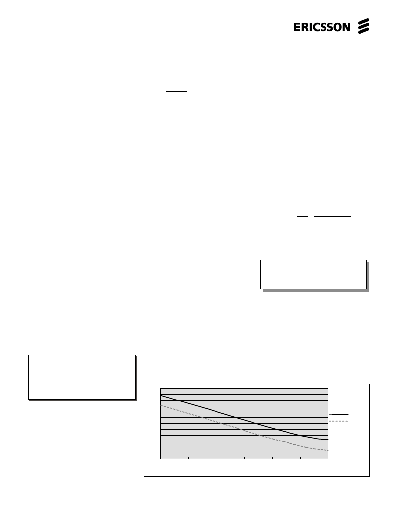
Programmable overhead voltage(POV)
With the POV function the overhead
voltage can be increased.
If the POV pin is left open the overhead
voltage is internally set to 3.2 V
Peak
in off-
The current limit (reference C in figure
13) is adjusted by connecting a resistor,
R
, between terminal PLC and ground
according to the equation:
R
LC
= 1000
I
LProg
+ 4
where R
LC
is in k
for I
LProg
in mA.
A second, lower battery voltage may be
connected to the device at terminal
VBAT2 to reduce short loop power
dissipation. The SLIC automatically
switches between the two battery supply
voltages without need for external
control. The silent battery switching
occurs when the line voltage passes the
value |VB2| - 40·I
L
- (V
OHVirt
-1.3),
if I
L
> 6 mA.
For correct functionality it is important
to connect the terminal VBAT2 to the
second power supply via the diode D
VB2
in figure 12.
An optional diode D
connected
between terminal VB and the VB2 power
supply, see figure 12, will make sure that
the SLIC continues to work on the
second battery even if the first battery
voltage disappears.
If a second battery voltage is not used,
VBAT2 is connected to VBAT on the
SLIC and C
VB2
, D
BB
and D
VB2
are removed.
Metering applications
For designs with metering applications
please contact Ericsson Microelectronics
for assistance.
CODEC Receive Interface
The PBL 386 50/2 SLIC have got a
completely new receive interface at the
four wire side which makes it possible to
reduce the number of capacitors in the
applications and to fit both single and
dual battery feed CODECs. The RSN
terminal, connecting to the CODEC
=
+
+
=
+
R
+
I
I
I
I
R
V
R
RSN
RT
RRX
RR
T
CODEC
RX
R
125
,
125
,
125
,
R
I
R
V
R
R
RSN
T
CODEC
RX
=
125
,
125
,
125
,
Battery Feed
The PBL 386 50/2 SLIC emulate
resistive loop feed, programmable
between 2·50
and 2·900
, with
adjustable current limitation. In the
current limited region the loop current
has a slight slope corresponding to
2·30 k
, see figure 13 reference B.
The open loop voltage measured
between the TIPX and RINGX terminals
is tracking the battery voltage V
. The
signalling headroom, or overhead voltage
V
, is programmable with a resistor R
OV
connected between terminal POV on the
SLIC and ground. Please refer to section
“Programmable overhead voltage(POV)”.
The battery voltage overhead, V
OH
,
depends on the programmed signal
overhead voltage V
. V
defines the
TIP to RING voltage at open loop
conditions according to V
TR
(at I
L
= 0 mA)
= |V
| - V
.
Refer to table 2 for typical values on
V
and V
. The overhead voltage is
changed when the line current is ap-
proaching open loop conditions. To
ensure maximum open loop voltage,
even with a leaking telephone line, this
occurs at a line current of approximately
6 mA. When the overhead voltage has
changed, the line voltage is kept nearly
constant with a steep slope correspond-
ing to 2·25
(reference G in figure 13).
The virtual battery overhead, V
, is
defined as the difference between the
battery voltage and the crossing point of
all possible resistive feeding slopes, see
figure 13 reference J. The virtual battery
overhead is a theoretical constant
needed to be able to calculate the
feeding characteristics.
SLIC
V
OH(typ)
[V]
V
OHVirt(typ)
[V]
PBL 386 50/2 3.0 +V
TRO
4.9 +V
TRO
Table 2. Battery overhead.
The resistive loop feed (reference D in
figure 13) is programmed by connecting
a resistor, R
, between terminals PSG
and VBAT according to the equation:
R
= R
SG
+ 2·10
4
+ 2R
F
200
where R
Feed
is in
for R
SG
and R
F
in
.
0
10
20
30
Rov (K
)
40
50
60
0
1
2
3
4
5
6
7
8
9
10
11
12
off-hook
on-hook
V
T
P
)
Figure 11. Programmable overhead voltage (POV). R
L
= 600
or
∞
.
相关PDF资料 |
PDF描述 |
|---|---|
| PBL386612QNS | Subscriber Line Interface Circuit |
| PBL386612QNT | Subscriber Line Interface Circuit |
| PBL38661-2 | LUG,BATTERY CABLE |
| PBL386612 | Subscriber Line Interface Circuit |
| PBL386652QNS | Subscriber Line Interface Circuit |
相关代理商/技术参数 |
参数描述 |
|---|---|
| PBL386502SOTR2A | 制造商:Rochester Electronics LLC 功能描述:- Tape and Reel |
| PBL386612 | 制造商:ERICSSON 制造商全称:Ericsson 功能描述:Subscriber Line Interface Circuit |
| PBL38661-2 | 制造商:ERICSSON 制造商全称:Ericsson 功能描述:Subscriber Line Interface Circuit |
| PBL386612QNS | 制造商:ERICSSON 制造商全称:Ericsson 功能描述:Subscriber Line Interface Circuit |
| PBL386612QNT | 制造商:ERICSSON 制造商全称:Ericsson 功能描述:Subscriber Line Interface Circuit |
发布紧急采购,3分钟左右您将得到回复。