- 您现在的位置:买卖IC网 > PDF目录378041 > PBL388141N (ERICSSON) Voice - switched 2-channel Circuit with loudspeaker amplifier PDF资料下载
参数资料
| 型号: | PBL388141N |
| 厂商: | ERICSSON |
| 英文描述: | Voice - switched 2-channel Circuit with loudspeaker amplifier |
| 中文描述: | 语音-开关2声道扬声器放大器电路 |
| 文件页数: | 12/14页 |
| 文件大小: | 239K |
| 代理商: | PBL388141N |
12
PBL 388 14
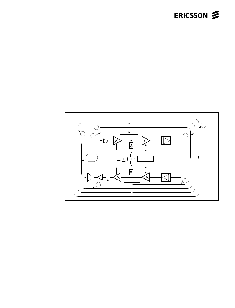
To design the speech control function,
seven different signal paths have to be
considered and understood. See fig. 28.
The signal paths:
G1
is the acoustic signal into the
microphone, further transformed to an
electrical signal in an amplifier which gain
can be controlled 12,5 dB up or down from
an idle point, further to a point where it is
rectified to a negative signal and compared
with its counterpart from the receiver
channel.
G2
is the corresponding signal to G1
on the receiver side. The signal from the
line that goes via the sidetone balancing
network and an amplifier which gain can be
controlled 12,5 dB up or down from an idle
point, further to a point where its rectified to
a positive signal and compared with its
counterpart from the transmitter channel.
G3
starts the same as G1 but does not
go to the rectifier, instead passes through
further an amplifier which gain can be
controlled 12,5 dB up or down from an idle
point, further to the transmitter of the speech
circuit and out on the telephone line.
G4
is the corresponding signal to G3
on the receiver side. Starts the same as G2
but does not go to the rectifier, instead
passes through further an amplifier which
gain can be controlled 12,5 dB up or down
from an idle point, via loudspeaker volume
control, loudspeaker amplifier and out as
an acoustic signal of the loudspeaker.
G5
starts the same way as G4 ends.
From the receiver rectifier through
loudspeaker amplifier, loudspeaker,
acoustic signal path (loudspeaker -
microphone) and is terminated, like G1, at
transmitter rectifier.
G6
is the corresponding signal to G5
but goes through the sidetone network.
Starts the same way as G3 ends. From the
transmitter rectifier, amplifier via speech
circuit transmitter, sidetone balancing
network and the line, to be terminated at
receiver rectifier like G2.
G7
is the closed loop signal that can
be considered to start or end at any point in
the loop. The summ of G5 and G6.
Hints how to design a handsfree system with PBL 388 14.
Figure 20. Schematic
diagram of the various
signal paths that affect on
the design of a handsfree
telephone.
General:
The first thing that comes into ones
mind when looking at a ”handsfree” solu-
tion like the one with PBL 388 13 is, that it
must be able to prevent oscillation in the
closed loop G7. The circuit does this by
having 50 dB less gain in the opposite
direction against the open channel this
being either the receiving or transmitting
direction. Nor does it oscillate when having
proper gain values, sidetone balance,
loudspeaker volume and small acoustic
coupling between the loudspeaker and
microphone. Actually, one needs a lot of
margin against oscillation so that no positive
feedback is created in the loop G7. This
would destroy the frequency characteristic
through the increasing gain at the "would
oscillate frequency" in case of somewhat
higher gain in the loop. The speech would
sound harsh. This is normally not the most
difficult requirement on the gain in the G7
loop. The most difficult requirement is set
by the telephone set impedance towards
the line. The signal originates from the line,
rounds the loop G7 and enters the line
again. This way the impedance of the
telephone set towards the line is influenced
by the gain in the loop G7. The impedance
of the telephone towards the line has to
measured in the ”handsfree” mode under
correct acoustic circumstances and at
maximum loudspeaker volume.
A major problem in many cases is
the acoustical coupling between
loudspeaker and microphone.The
telephone designer gets often an order to fit
a ”handsfree” telephone system into a fully
unsuitable ready made casing. The design
of a ”hansfree” telephone with a speech
control starts with the acoustical design of
the casing. PBL 388 14 makes a good
acoustical design to sound as close a perfect
”handsfree” as it is possible. This means
that there are no audible swiching noises
and speech is conveyed in one direction at
the time. In opposite case having a bad
acoustic design with a large coupling
between the loudspeaker and the
microphone, no electronics in the world,
using the speech switching principle, can
make it to sound good. Why, will be studied
later.
Acoustic design:
Any amount of time can be spent on
the acoustic design. It depends largely if
the task is to make a "just working
handsfree” telephone or to make the best
COMPARATOR
VOLUME
acoustical
coupling
G
1
G
6
G
7
G
2
G
3
G
4
G
5
Receiver channel
Transmitter channel
相关PDF资料 |
PDF描述 |
|---|---|
| PBL388141SO | Voice - switched 2-channel Circuit with loudspeaker amplifier |
| PBL388141SOT | Voice - switched 2-channel Circuit with loudspeaker amplifier |
| PBL40215 | RF Transceiver circuit for the Digital Enhanced Cordless Telecommunications (DECT) system |
| PBL40305 | Multiband GSM Power Amplifier |
| PBL40307 | GSM Dual Band Tx_VCO |
相关代理商/技术参数 |
参数描述 |
|---|---|
| PBL388141SO | 制造商:ERICSSON 制造商全称:Ericsson 功能描述:Voice - switched 2-channel Circuit with loudspeaker amplifier |
| PBL388141SOT | 制造商:ERICSSON 制造商全称:Ericsson 功能描述:Voice - switched 2-channel Circuit with loudspeaker amplifier |
| PBL3-RP15 | 制造商:Middle Atlantic Products 功能描述: |
| PBL4 | 制造商:Brady Corporation 功能描述: |
| PBL-4 | 制造商:Middle Atlantic Products 功能描述: |
发布紧急采购,3分钟左右您将得到回复。