- 您现在的位置:买卖IC网 > PDF目录378042 > PBM3960-1 (ERICSSON) KPTC6F10-6PD PDF资料下载
参数资料
| 型号: | PBM3960-1 |
| 厂商: | ERICSSON |
| 英文描述: | KPTC6F10-6PD |
| 中文描述: | 的微控制器/双数字到模拟转换器 |
| 文件页数: | 6/10页 |
| 文件大小: | 111K |
| 代理商: | PBM3960-1 |
PBM 3960/1
6
Where (L
… L
) is the level pro-
grammed in channel 2’s level register.
(D
… D
) and (Q
… Q
) are the new
and old values of DA-Data2.
The two level registers, LEVEL1 and
LEVEL2, consist of three flip flops each
and they are compared against the
three most significant bits of the DA-
Data value, sign bit excluded.
DA
1
and DA
2
These are the two outputs of DAC1 and
DAC2. Input to the DACs are internal
data bus (Q
61
… Q
01
) and (Q
62
… Q
02
).
Reference Voltage V
Ref
V
is the analog input for the two
DACs. Special care in layout, gives a
very low voltage drop from pin to
resistor. Any V
between 0.0 V and V
can be applied, but output might be non-
linear above 3.0 V.
Power-on Reset
This function automatically resets all
internal flip flops at power-on. This
results in V
voltage at both DAC
outputs and all digital outputs.
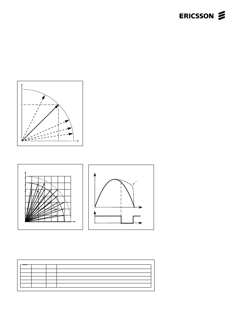
Figure 10. Table showing how data is transfered inside PBM 3960/1.
Figure 9. Motor current dragging at high
step rates and current decay influence.
Fast current decay will make it possible
for the current to follow the ideal sine
curve. Output shown without sign shift.
Figure 8b. An example of accessible
positions with a given torque deviation/
fullstep. Note that 1:st
μ
step sets highest
resolution. Data points are exaggerated
for illustration purpose.
TNom = code 127.
Where (D
… D
) is the new value being
sent to DA-Data1 and (Q
… Q
) is DA-
Data1’s old value. (L
… L
) are the
three bits for setting the current decay
level at LEVEL1.
The logic definition of CD
2
is analog to
CD
1
:
CD
2
= NOT{[(D
… D
) < (Q
… Q
02
)]
AND[(D
6
…D
4
) < (L
62
… L
42
)]}
Reset
If Reset is not used, leave it disconnec-
ted. Reset can be used to measure
leakage currents from V
DD
.
Applications Information
How Many Microsteps
The number of true microsteps that can
be obtained depends upon many
different variables, such as the number
of data bits in the Digital-to-Analog
converter, errors in the converter,
acceptable torque ripple, single- or
double-pulse programming, the motor’s
electrical, mechanical and magnetic
characteristics, etc. Many limits can be
found in the motor’s ability to perform
properly; overcome friction, repeatability,
torque linearity, etc. It is important to
realize that the number of current levels,
128 (2
7
), is notthe number of steps
available. 128 is the number of current
levels (reference voltage levels)
available from each driver stage.
Combining a current level in one winding
with any of 128 other current levels in
the other winding will make up 128
current levels. So expanding this, it is
possible to get 16,384 (128 128)
combinations of different current levels in
the two windings. Remember that these
16,384 micro-positions are not all useful,
the torque will vary from 100% to 0%
and some of the options will make up the
same position. For instance, if the
current level in one winding is OFF (0%)
you can still vary the current in the other
winding in 128 levels. All of these
combinations will give you the same
position buta varying torque.
Typical Application
The microstepper solution can be used
in a system with or without a micro-
processor.
Without a microprocessor,
a counter
addresses a ROM where appropriate
step data is stored. Step and Direction
are the input signals which represent
clock and up / down of counter. This is
the ideal solution for a system where
there is no microprocessor or it is heavily
loaded with other tasks.
With a microprocessor
, data is stored
in ROM / RAM area or each step is
successively calculated. PBM 3960/1 is
connected like any peripheral addressa-
ble device. All parts of stepping can be
tailored for specific damping needs etc.
T [mNm]
T [mNm]
max
T
nom
T
min
T
DA output [V]
t
Current dragging
Time
CD
CS A0 A1 Data Transfer
0 0 0 D7 —> Sign1, (D6—D0) —> (Q61—Q01), New value —> CD1
0 0 1 (D6—D4) —> (L61—L41)
0 1 0 D7 —> Sign2, (D6—D0) —> (Q62—Q02), New value —> CD2
0 1 1 (D6—D4) —> (L62—L42)
1 X X No Transfer
I [mA]
I [mA]
I
Figure 8a. Assuming that torque is
proportional to the current in resp.
winding it is possible to draw figure 8b.
相关PDF资料 |
PDF描述 |
|---|---|
| PBM3960N | KPTC 6C 6#20 PIN PLUG |
| PBM3960QN | KPTC 6C 6#20 SKT PLUG |
| PC100-222-620 | KPT 3C 3#20 SKT PLUG |
| PC100-323-620 | 3.3V 2M x 64/72-Bit 1 BANK SDRAM Module 3.3V 4M x 64/72-Bit 2 BANK SDRAM Module |
| PC111L | Long Creepage Distance Type Photocoupler |
相关代理商/技术参数 |
参数描述 |
|---|---|
| PBM39601NS | 制造商:ERICSSON 制造商全称:Ericsson 功能描述:Microstepping Controller/Dual Digital-to-Analog Converter |
| PBM39601QNS | 制造商:ERICSSON 制造商全称:Ericsson 功能描述:Microstepping Controller/Dual Digital-to-Analog Converter |
| PBM39601QNT | 制造商:ERICSSON 制造商全称:Ericsson 功能描述:Microstepping Controller/Dual Digital-to-Analog Converter |
| PBM3960N | 制造商:ERICSSON 制造商全称:Ericsson 功能描述:Microstepping Controller/Dual Digital-to-Analog Converter |
| PBM3960QN | 制造商:ERICSSON 制造商全称:Ericsson 功能描述:Microstepping Controller/Dual Digital-to-Analog Converter |
发布紧急采购,3分钟左右您将得到回复。