- 您现在的位置:买卖IC网 > PDF目录369948 > PCA9553D02 (NXP Semiconductors N.V.) 4-bit I2C LED driver with programmable blink rates PDF资料下载
参数资料
| 型号: | PCA9553D02 |
| 厂商: | NXP Semiconductors N.V. |
| 元件分类: | LED驱动器 |
| 英文描述: | 4-bit I2C LED driver with programmable blink rates |
| 中文描述: | 4位I2C LED与可编程闪烁率司机 |
| 文件页数: | 4/18页 |
| 文件大小: | 130K |
| 代理商: | PCA9553D02 |
Philips Semiconductors
Product data sheet
PCA9553
4-bit I
2
C LED driver with programmable blink rates
2004 Oct 01
4
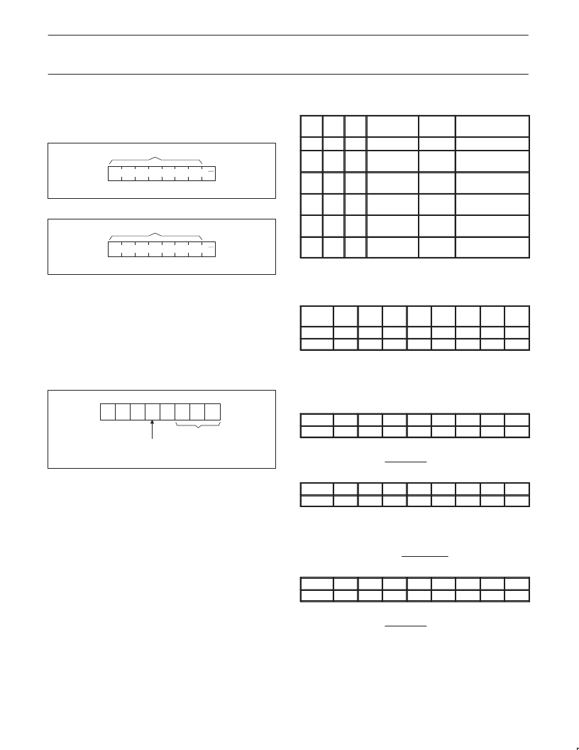
DEVICE ADDRESSING
Following a START condition the bus master must output the
address of the slave it is accessing. The address of the PCA9553/01
is shown in Figure 3 and PCA9553/02 in Figure 4.
1
1
0
0
0
1
0
SLAVE ADDRESS
SW01037
R/W
Figure 3. Slave address — PCA9553/01
1
1
0
0
0
1
1
SLAVE ADDRESS
SW01038
R/W
Figure 4. Slave address — PCA9553/02
The last bit of the address byte defines the operation to be
performed. When set to logic 1 a read is selected, while a logic 0
selects a write operation.
CONTROL REGISTER
Following the successful acknowledgement of the slave address,
the bus master will send a byte to the PCA9553 which will be stored
in the Control Register.
0
0
AI
B2
B1 B0
0
SW01034
0
AUTO-INCREMENT FLAG
REGISTER ADDRESS
RESET STATE: 00h
Figure 5. Control register
The lowest 3 bits are used as a pointer to determine which register
will be accessed.
If the auto-increment flag is set, the three low order bits of the
Control Register are automatically incremented after a read or write.
This allows the user to program the registers sequentially. The contents
of these bits will rollover to ‘000’ after the last register is accessed.
When auto-increment flag is set (AI = 1) and a read sequence is
initiated, the sequence must start by reading a register different from
‘0’ (B2 B1 B0
0 0 0)
Only the 3 least significant bits are affected by the AI flag.
Unused bits must be programmed with zeroes.
Control Register definition
B2
B1
B0
REGISTER
NAME
TYPE
REGISTER
FUNCTION
0
0
0
INPUT
READ
INPUT REGISTER
0
0
1
PSC0
READ/
WRITE
FREQUENCY
PRESCALER 0
0
1
0
PWM0
READ/
WRITE
PWM REGISTER 0
0
1
1
PSC1
READ/
WRITE
FREQUENCY
PRESCALER 1
1
0
0
PWM1
READ/
WRITE
PWM REGISTER 1
1
0
1
LS0
READ/
WRITE
LED SELECTOR
REGISTER DESCRIPTION
INPUT — INPUT REGISTER
LED
3
3
X
LED
2
2
X
LED
1
1
X
LED
0
0
X
bit
7
0
6
0
5
0
4
0
default
The INPUT register reflects the state of the device pins. Writes to
this register will be acknowledged but will have no effect.
NOTE:
The default value “X” is determined by the externally applied
logic level, normally ‘1’ when used for directly driving LED with
pull-up to V
DD
.
PSC0 — FREQUENCY PRESCALER 0
bit
7
6
5
default
1
1
1
PSC0 is used to program the period of the PWM output.
4
1
3
1
2
1
1
1
0
1
The period of BLINK0
(PSC0
1)
44
PWM0 — PWM REGISTER 0
bit
7
default
1
The PWM0 register determines the duty cycle of BLINK0. The
outputs are LOW (LED off) when the count is less than the value in
PWM0 and HIGH when it is greater. If PWM0 is programmed with
00h, then the PWM0 output is always LOW.
The duty cycle of BLINK0 is: 256 256
6
0
5
0
4
0
3
0
2
0
1
0
0
0
PSC1 — FREQUENCY PRESCALER 1
bit
7
6
default
1
1
PSC1 is used to program the period of PWM output.
5
1
4
1
3
1
2
1
1
1
0
1
The period of BLINK1
(PSC1
1)
44
相关PDF资料 |
PDF描述 |
|---|---|
| PCA9553DP01 | 4-bit I2C LED driver with programmable blink rates |
| PCA9553DP02 | 4-bit I2C LED driver with programmable blink rates |
| PCA9561 | Quad 6-bit multiplexed I2C EEPROM DIP switch |
| PCB2421 | 1K dual mode serial EEPROM |
| PCB2421P | 1K dual mode serial EEPROM |
相关代理商/技术参数 |
参数描述 |
|---|---|
| PCA9553DP | 制造商:PHILIPS 制造商全称:NXP Semiconductors 功能描述:4-bit I2C LED driver with programmable blink rates |
| PCA9553DP/01 | 制造商:PHILIPS 制造商全称:NXP Semiconductors 功能描述:4-bit I2C-bus LED driver with programmable blink rates |
| PCA9553DP/01,118 | 功能描述:LED照明驱动器 4BIT I2C FM OD LED BLK RoHS:否 制造商:STMicroelectronics 输入电压:11.5 V to 23 V 工作频率: 最大电源电流:1.7 mA 输出电流: 最大工作温度: 安装风格:SMD/SMT 封装 / 箱体:SO-16N |
| PCA9553DP/01118 | 制造商:Rochester Electronics LLC 功能描述: 制造商:NXP 功能描述: 制造商:NXP Semiconductors 功能描述: |
| PCA9553DP/02 | 制造商:PHILIPS 制造商全称:NXP Semiconductors 功能描述:4-bit I2C-bus LED driver with programmable blink rates |
发布紧急采购,3分钟左右您将得到回复。