- 您现在的位置:买卖IC网 > PDF目录98051 > PCI930PBK (TEXAS INSTRUMENTS INC) 3-CHANNEL, AUDIO/VIDEO SWITCH, PQFP128 PDF资料下载
参数资料
| 型号: | PCI930PBK |
| 厂商: | TEXAS INSTRUMENTS INC |
| 元件分类: | 多路复用及模拟开关 |
| 英文描述: | 3-CHANNEL, AUDIO/VIDEO SWITCH, PQFP128 |
| 封装: | PLASTIC, TQFP-128 |
| 文件页数: | 13/13页 |
| 文件大小: | 191K |
| 代理商: | PCI930PBK |
PCI930
3-TO-1 ZOOMED VIDEO SWITCH
SCPS018B – OCTOBER 1997 – REVISED DECEMBER 1997
9
POST OFFICE BOX 655303
DALLAS, TEXAS 75265
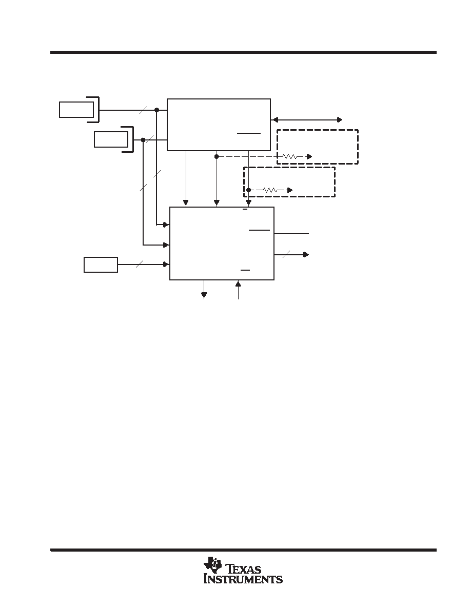
typical system configuration with PCI1220 PC Card controller
PCI1220
PCI Bus
PC Card
Socket A
PC Card
Socket B
23
PCI930
23
Third
ZV
Source
ZV Output to VGA Controller
and Audio CODEC
System Reset Control
Optional Pullup to Set
ZV_xx Inactive
VCC
Optional Pullup to Set
C Precedence
VCC
MFUNC5
GPO4
(160)
MFUNC2
ZVSTAT
(157)
MFUNC4
ZVSEL1
(159)
C_STAT
A/B_STAT A/B_SEL
A_xx
B_xx
C_xx
ZV_STAT
AZ_OE
ZV
Status
Pin
ZV_xx
Output
Enable
ZV_xx
RESET
68
Figure 2. Typical System Configuration for PCI930 With TI PCI1220 PC Card Controller
absolute maximum ratings over operating free-air temperature range (unless otherwise noted)
Supply voltage range, VCC
–0.5 V to 6 V
. . . . . . . . . . . . . . . . . . . . . . . . . . . . . . . . . . . . . . . . . . . . . . . . . . . . . . . . . .
Supply voltage range, VCCS
–0.5 V to 6 V
. . . . . . . . . . . . . . . . . . . . . . . . . . . . . . . . . . . . . . . . . . . . . . . . . . . . . . . . .
Input voltage range, VI
–0.5 V to 6.5 V
. . . . . . . . . . . . . . . . . . . . . . . . . . . . . . . . . . . . . . . . . . . . . . . . . . . . . . . . . . . . .
Output voltage range, VO
–0.5 V to VCC + 0.5 V
. . . . . . . . . . . . . . . . . . . . . . . . . . . . . . . . . . . . . . . . . . . . . . . . . . . .
Input Clamp Current, IIK (VI < 0 or VI > VCC) (see Note 3)
±20 mA
. . . . . . . . . . . . . . . . . . . . . . . . . . . . . . . . . . . .
Output Clamp Current, IOK (VO < 0 or VO > VCC) (see Note 4)
±20 mA
. . . . . . . . . . . . . . . . . . . . . . . . . . . . . . .
Storage temperature range
–65
°C to 150°C
. . . . . . . . . . . . . . . . . . . . . . . . . . . . . . . . . . . . . . . . . . . . . . . . . . . . . . . .
Virtual junction temperature, TJ
150
°C
. . . . . . . . . . . . . . . . . . . . . . . . . . . . . . . . . . . . . . . . . . . . . . . . . . . . . . . . . . . .
Stresses beyond those listed under “absolute maximum ratings” may cause permanent damage to the device. These are stress ratings only, and
functional operation of the device at these or any other conditions beyond those indicated under “recommended operating conditions” is not
implied. Exposure to absolute-maximum-rated conditions for extended periods may affect device reliability.
NOTES:
3. Applies for external input and bidirectional buffers. VI > VCC does not apply to fail-safe terminals. ZV terminals are measured with
respect to VCCS. The limit specified applies for a DC condition.
4. Applies for external output and bidirectional buffers. VO > VCC does not apply to fail-safe terminals. ZV terminals are measured with
respect to VCCS. The limit specified applies for a DC condition.
相关PDF资料 |
PDF描述 |
|---|---|
| PCZ33937AEKR2 | AC MOTOR CONTROLLER, 0.8 A, PDSO54 |
| PCZ34670EG | SWITCHING REGULATOR, 400 kHz SWITCHING FREQ-MAX, PDSO20 |
| PD69101ILQ | SWITCHING CONTROLLER, PQCC24 |
| PDT006A0X43-SRZ | DC-DC REG PWR SUPPLY MODULE |
| PDT012A0X3-SRZ | 1-OUTPUT DC-DC REG PWR SUPPLY MODULE |
相关代理商/技术参数 |
参数描述 |
|---|---|
| PCI93LV/C | 制造商:CALIBRE UK 功能描述:CARD PCI I2C-BUS 2-6V |
| PCI93LV/C | 制造商:CALIBRE UK 功能描述:CARD PCI I2C-BUS 2-6V |
| PCI950 | 制造商:TI 制造商全称:Texas Instruments 功能描述:IRQSER DESERIALIZER |
| PCI950-1F | 制造商:Texas Instruments 功能描述:INTEGRATED CIRCUIT PCI I/O ACCELERATOR PLX - Tape and Reel |
| PCI950PT | 功能描述:外围驱动器与原件 - PCI IRQSER Deserializer RoHS:否 制造商:PLX Technology 工作电源电压: 最大工作温度: 安装风格:SMD/SMT 封装 / 箱体:FCBGA-1156 封装:Tray |
发布紧急采购,3分钟左右您将得到回复。