- 您现在的位置:买卖IC网 > PDF目录15564 > PCJ1A471MCL1GS (Nichicon)CAP ALUM 470UF 10V 20% SMD PDF资料下载
参数资料
| 型号: | PCJ1A471MCL1GS |
| 厂商: | Nichicon |
| 文件页数: | 1/2页 |
| 文件大小: | 0K |
| 描述: | CAP ALUM 470UF 10V 20% SMD |
| 产品培训模块: | Conductive Polymer Aluminum Capacitors |
| 产品目录绘图: | CJ Series Part Number Markings CJ Series Bottom_10 CJ Series_10 x 8 |
| 标准包装: | 1 |
| 系列: | CJ |
| 电容: | 470µF |
| 额定电压: | 10V |
| 容差: | ±20% |
| 寿命@温度: | 105°C 时为 2000 小时 |
| 工作温度: | -55°C ~ 105°C |
| 特点: | 聚合物 |
| 纹波电流: | 3.8A |
| ESR(等效串联电阻): | 19 毫欧 |
| 安装类型: | 表面贴装 |
| 封装/外壳: | 径向,Can - SMD |
| 尺寸/尺寸: | 0.394" 直径(10.00mm) |
| 高度 - 座高(最大): | 0.315"(8.00mm) |
| 表面贴装占地面积: | 0.406" L x 0.406" W(10.30mm x 10.30mm) |
| 包装: | 标准包装 |
| 产品目录页面: | 1978 (CN2011-ZH PDF) |
| 其它名称: | 493-3050-6 |
�� �
�
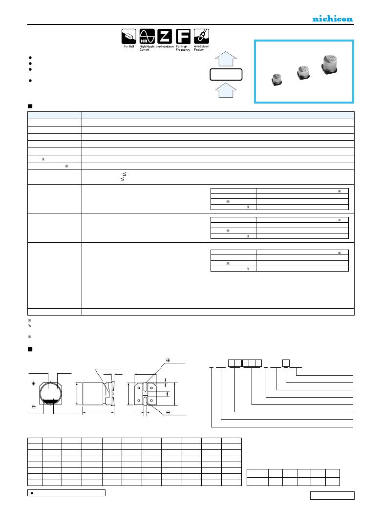
�CONDUCTIVE� POLYMER� ALUMINUM� SOLID� ELECTROLYTIC� CAPACITORS�
�CJ�
�Chip� Type,� Low� ESR,�
�Higher� Capacitance�
�series�
�CK�
�Low� ESR,� Higher� Capacitance,� High� ripple� current.�
�Load� life� of� 2000� hours� at� 105� °� C.�
�SMD� type� :� Lead� free� reflow� soldering� condition� at�
�260� °� C� peak� correspondence.�
�Compliant� to� the� RoHS� directive� (2011/65/EU).�
�Low� ESR�
�CJ�
�Low� ESR�
�Higher�
�Capacitance,�
�Specifications�
�Item�
�Category� Temperature� Range�
�Rated� Voltage� Range�
�–� 55� to� +105� °� C�
�2.5� to� 16V�
�CF�
�Performance� Characteristics�
�Rated� Capacitance� Range� 33� to� 2700μF�
�Capacitance� Tolerance�
�±� 20%� at� 120Hz,� 20� °� C�
�Tangent� of� loss� angle� (tan� δ� )� Less� than� or� equal� to� the� specified� value� at� 120Hz,� 20� °� C�
�ESR� (�
�1)�
�Less� than� or� equal� to� the� specified� value� at� 100kHz,� 20� °� C�
�Leakage� Current� (�
�2)�
�Less� than� or� equal� to� the� specified� value� .�
�After� 2� minutes'� application� of� rated� voltage� at� 20� °� C�
�Temperature� Characteristics�
�(Max.Impedance� Ratio)�
�Z+105� °� C� /� Z+20� °� C�
�Z� –� 55� °� C� /� Z+20� °� C�
�1.25�
�1.25�
�(100kHz)�
�Endurance�
�Damp� Heat�
�(Steady� State)�
�The� specifications� listed� at� right� shall� be� met� when� the�
�capacitors� are� restored� to� 20� °� C� after� the� rated� voltage� is�
�applied� for� 2000� hours� at� 105� °� C.�
�The� specifications� listed� at� right� shall� be� met� when� the�
�capacitors� are� restored� to� 20� °� C� after� the� rated� voltage� is�
�applied� for� 1000� hours� at� 60� °� C,� 90%� RH.�
�Capacitance� change�
�tan� δ�
�ESR� (� 1)�
�Leakage� current� (� 2)�
�Capacitance� change�
�tan� δ�
�ESR� (� 1)�
�Leakage� current� (� 2)�
�Within� ±� 20%� of� the� initial� capacitance� value� (� 3)�
�150%� or� less� than� the� initial� specified� value�
�150%� or� less� than� the� initial� specified� value�
�Less� than� or� equal� to� the� initial� specified� value�
�Within� ±� 20%� of� the� initial� capacitance� value� (� 3)�
�150%� or� less� than� the� initial� specified� value�
�150%� or� less� than� the� initial� specified� value�
�Less� than� or� equal� to� the� initial� specified� value�
�After� soldering� the� capacitor� under� the� soldering� conditions�
�Resistance� to�
�Soldering� Heat�
�prescribed� here,� the� capacitor� shall� meet� the� specifications� listed� at�
�right,� provided� that� it's� temperature� profile� is� measured� at� the�
�capacitor� top� and� the� terminal.�
�Pre-heating� shall� be� done� at� 150� to� 200� °� C� and� for� 60� to� 180� sec.�
�The� duration� for� over� +230� °� C� temperature� at� capacitor� surface� shall�
�not� exceed� 60� seconds.�
�In� the� case� of� peak� temp,� less� than� 250� °� C,� reflow� soldering� shall� be�
�Capacitance� change�
�tan� δ�
�ESR� (� 1)�
�Leakage� current� (� 2)�
�Within� ±� 10%� of� the� initial� capacitance� value� (� 3)�
�130%� or� less� than� the� initial� specified� value�
�130%� or� less� than� the� initial� specified� value�
�Less� than� or� equal� to� the� initial� specified� value�
�two� times� maximum.�
�In� the� case� of� peak� temp,� less� than� 260� °� C,� reflow� soldering� shall� be�
�once.�
�Measurement� for� solder� temperature� profile� shall� be� made� at� the�
�capacitor� top� and� the� terminal.�
�Marking�
�Navy� blue� print� on� the� case� top�
�1� ESR� should� be� measured� at� both� of� the� terminal� ends� closest� where� the� terminals� protrude� through� the� plastic� platform.�
�2� Conditioning� :� If� any� doubt� arises,� measure� the� leakage� current� after� the� voltage� treatment� of� applying� DC� rated� voltage� continuously� to� the� capacitor� for� 120�
�minutes� at� 105� °� C.�
�3� Initial� value� :� The� value� before� test� of� examination� of� resistance� to� soldering.�
�Dimensions�
�Type� numbering� system� (Example� :� 6.3V� 220μF)�
�1�
�2�
�3�
�4�
�5�
�6�
�7�
�8�
�9� 10� 11� 12� 13� 14�
�Plastic� platform�
�Positive�
�P� C� J� 0� J� 2� 2� 1� M� C� L� 1� G� S�
�Capacitance�
�Lot� No.�
�0.3� MAX.�
�C� ±� 0.2�
�Taping� code�
�Size� code�
�Configuration�
�Capacitance� tolerance� (� ±� 20%)�
�Rated� capacitance� (220� μ� F)�
�Series�
�Voltage� (� j:6.3v)�
�-� 0.4�
�L� +0.1�
�Negative�
�Rated� voltage� (6.3V)�
�H�
�(mm)�
�Series� name�
�Type�
�Size�
�φ� 5� ×� 6L�
�φ� 6.3� ×� 6L� φ� 6.3� ×� 8L�
�φ� 8� ×� 7L�
�φ� 8� ×� 8L�
�φ� 8� ×� 10L�
�φ� 8� ×� 12L�
�φ� 10� ×� 8L� φ� 10� ×� 10L� φ� 10� ×� 12.7L�
�φ� D�
�L�
�A�
�5.0�
�5.9�
�6.0�
�6.3�
�5.9�
�7.3�
�6.3�
�7.9�
�7.3�
�8.0�
�6.9�
�9.0�
�8.0�
�7.9�
�9.0�
�8.0�
�9.9�
�9.0�
�8.0�
�11.9�
�9.0�
�10.0�
�7.9�
�11.0�
�10.0�
�9.9�
�11.0�
�10.0�
�12.6�
�11.0�
�B�
�5.3�
�6.6�
�6.6�
�8.3�
�8.3�
�8.3�
�8.3�
�10.3�
�10.3�
�10.3�
�Voltage�
�C�
�E�
�5.3�
�1.6�
�6.6�
�2.1�
�6.6�
�2.1�
�8.3�
�3.2�
�8.3�
�3.2�
�8.3�
�3.2�
�8.3�
�3.2�
�10.3�
�4.6�
�10.3�
�4.6�
�10.3�
�4.6�
�V�
�2.5�
�4�
�6.3�
�10�
�16�
�H�
�0.5� to� 0.8� 0.5� to� 0.8� 0.5� to� 0.8� 0.8� to� 1.1� 0.8� to� 1.1� 0.8� to� 1.1� 0.8� to� 1.1� 0.8� to� 1.1� 0.8� to� 1.1� 0.8� to� 1.1�
�Code�
�e�
�g�
�j�
�A�
�C�
�Dimension� table� in� next� page.�
�CAT.8100C�
�相关PDF资料 |
PDF描述 |
|---|---|
| H2BXT-10103-V4-ND | JUMPER-H1500TR/A2015V/X 3" |
| H2BXT-10103-S4-ND | JUMPER-H1500TR/A2015S/X 3" |
| RBM18DSEI | CONN EDGECARD 36POS .156 EYELET |
| PCJ0G152MCL1GS | CAP ALUM 1500UF 4V 20% SMD |
| RMM10DRXN | CONN EDGECARD 20POS DIP .156 SLD |
相关代理商/技术参数 |
参数描述 |
|---|---|
| PCJ1A560MCL1GS | 功能描述:铝有机聚合物电容器 10volts 56uF 105c 5x6 RoHS:否 制造商:Panasonic Electronic Components 电容:470 uF 容差:20 % 电压额定值:2.5 V ESR:4.5 mOhms 工作温度范围:- 40 C to + 105 C 端接类型:SMD/SMT 外壳直径: 外壳长度:7.3 mm 外壳宽度:4.3 mm 外壳高度:1.9 mm 封装:Reel |
| PCJ1A680MCL1GS | 功能描述:铝有机聚合物电容器 10volts 68uF SMD Low ESR RoHS:否 制造商:Panasonic Electronic Components 电容:470 uF 容差:20 % 电压额定值:2.5 V ESR:4.5 mOhms 工作温度范围:- 40 C to + 105 C 端接类型:SMD/SMT 外壳直径: 外壳长度:7.3 mm 外壳宽度:4.3 mm 外壳高度:1.9 mm 封装:Reel |
| PCJ1A681MCL1GS | 功能描述:铝有机聚合物电容器 680uF 10 Volts 20% SMD Low ESR RoHS:否 制造商:Panasonic Electronic Components 电容:470 uF 容差:20 % 电压额定值:2.5 V ESR:4.5 mOhms 工作温度范围:- 40 C to + 105 C 端接类型:SMD/SMT 外壳直径: 外壳长度:7.3 mm 外壳宽度:4.3 mm 外壳高度:1.9 mm 封装:Reel |
| PCJ1C101MCL1GS | 功能描述:铝有机聚合物电容器 16volts 100uF 105c 8x7 RoHS:否 制造商:Panasonic Electronic Components 电容:470 uF 容差:20 % 电压额定值:2.5 V ESR:4.5 mOhms 工作温度范围:- 40 C to + 105 C 端接类型:SMD/SMT 外壳直径: 外壳长度:7.3 mm 外壳宽度:4.3 mm 外壳高度:1.9 mm 封装:Reel |
| PCJ1C101MCL4GS | 功能描述:铝有机聚合物电容器 16volts 100uF 105c 6.3x8 RoHS:否 制造商:Panasonic Electronic Components 电容:470 uF 容差:20 % 电压额定值:2.5 V ESR:4.5 mOhms 工作温度范围:- 40 C to + 105 C 端接类型:SMD/SMT 外壳直径: 外壳长度:7.3 mm 外壳宽度:4.3 mm 外壳高度:1.9 mm 封装:Reel |
发布紧急采购,3分钟左右您将得到回复。