- 您现在的位置:买卖IC网 > PDF目录2015 > PCM3168ATPAPRQ1G4 (Texas Instruments)IC 24-BIT AUDIO CODEC 64-HTQFP PDF资料下载
参数资料
| 型号: | PCM3168ATPAPRQ1G4 |
| 厂商: | Texas Instruments |
| 文件页数: | 14/68页 |
| 文件大小: | 0K |
| 描述: | IC 24-BIT AUDIO CODEC 64-HTQFP |
| 标准包装: | 1,000 |
| 类型: | 音频编解码器 |
| 数据接口: | 串行 |
| 分辨率(位): | 24 b |
| ADC / DAC 数量: | 6 / 8 |
| 三角积分调变: | 是 |
| S/N 比,标准 ADC / DAC (db): | 107 / 112(差分),104 / 112(单端) |
| 动态范围,标准 ADC / DAC (db): | 107 / 112(差分),104 / 112(单端) |
| 电压 - 电源,模拟: | 4.5 V ~ 5.5 V |
| 电压 - 电源,数字: | 3 V ~ 3.6 V |
| 工作温度: | -40°C ~ 105°C |
| 安装类型: | 表面贴装 |
| 封装/外壳: | 64-TQFP 裸露焊盘 |
| 供应商设备封装: | 64-HTQFP(10x10) |
| 包装: | 带卷 (TR) |
第1页第2页第3页第4页第5页第6页第7页第8页第9页第10页第11页第12页第13页当前第14页第15页第16页第17页第18页第19页第20页第21页第22页第23页第24页第25页第26页第27页第28页第29页第30页第31页第32页第33页第34页第35页第36页第37页第38页第39页第40页第41页第42页第43页第44页第45页第46页第47页第48页第49页第50页第51页第52页第53页第54页第55页第56页第57页第58页第59页第60页第61页第62页第63页第64页第65页第66页第67页第68页
0
20
40
60
80
100
120
140
160
180
200
-
2.0
Amplitude(dB)
NormalizedFrequency(f )
S
0
0.5
1.0
1.5
DSM_Dual
DSM_Single
DF_Single
DF_Dual
0
20
40
60
80
100
120
140
160
180
200
-
2.0
Amplitude(dB)
NormalizedFrequency(f )
S
0
0.5
1.0
1.5
DSM_Dual
DSM_Single
DSM_Quad
DF_Dual
DF_Single
DF_Quad
www.ti.com ......................................................................................................................................................................................... SBAS452 – SEPTEMBER 2008
oversampling frequency of x64; this mode is supported for sampling frequencies less than 100 kHz. In quad rate
mode, the DAC operates at an oversampling frequency of x32. The sampling mode is automatically selected
according to the ratio of system clock frequency and sampling frequency by default (for example, single rate for
512 fS and 768 fS, dual rate for 256 fS and 384 fS, and quad rate for 128 fS and 192 fS), but manual selection is
also possible for specified combinations through the serial mode control resistor.
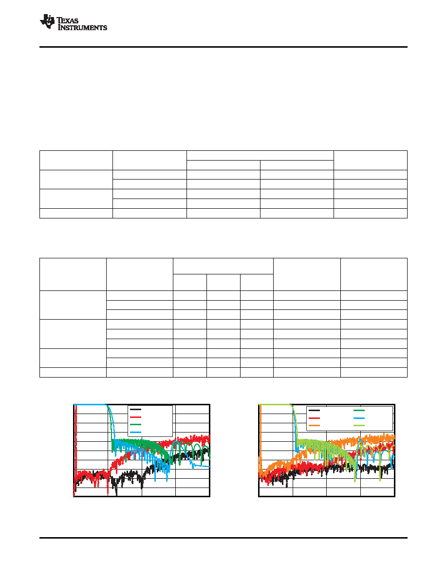
ΔΣ modulator, noise-free
shaped bandwidth, and each sampling mode setting for ADC operation. Table 6 and Figure 32 describe the
relation between the oversampling rate of the digital filter and
ΔΣ modulator, noise-free shaped bandwidth, and
each sampling mode setting for DAC operation.
Table 5. ADC Modulator OSR and Noise-Free Shaped Bandwidthfor Each Sampling Mode
NOISE-FREE SHAPED BANDWIDTH (kHz)
SAMPLING MODE
SYSTEM CLOCK RATE
REGISTER SETTING
(fS)
fS = 48 kHz
fS = 96 kHz
MODULATOR OSR
512, 768
40
N/A
x128
Auto
256, 384
20
40
x64
512, 768
40
N/A
x128
Single
256, 384
40
N/A
x128
Dual
256, 384
20
40
x64
Table 6. DAC Digital Filter OSR, Modulator OSR, and Noise-Free Shaped Bandwidth
for Each Sampling Mode
NOISE-FREE SHAPED
BANDWIDTH
SAMPLING MODE
SYSTEM CLOCK
fS = 48
fS = 96
fS = 192
REGISTER SETTING
RATE (fS)
kHz
DIGITAL FILTER OSR
MODULATOR OSR
512, 768
40
N/A
x8
x128
Auto
256, 384
20
40
N/A
x8
x64
128, 192(1)(2)
10
20
40
x4
x32
512, 768
40
N/A
x8
x128
Single
256, 384
40
N/A
x8
x128
128, 192(1)(2)
20
N/A
x4
x64
256, 384
20
40
N/A
x8
x64
Dual
128, 192(1)(2)
20
40
N/A
x4
x64
Quad
128, 192(1)(2)
10
20
40
x4
x32
(1)
Supported only by DAC operation.
(2)
Quad mode filter characteristic is applied.
Figure 31. ADC
ΔΣ Modulator and Digital Filter
Figure 32. DAC
ΔΣ Modulator and Digital Filter
Characteristic
Copyright 2008, Texas Instruments Incorporated
21
Product Folder Link(s): PCM3168A PCM3168A-Q1
相关PDF资料 |
PDF描述 |
|---|---|
| PI6C20400LE | IC CLOCK BUFF DIFF 28-TSSOP |
| PI6C21200VE | IC 1:12 CLOCK DVR PCI-EX 56-SSOP |
| PI6C410MAE | IC CLK GEN INTEL PCI-EX 56-TSSOP |
| PI6C557-03LE | IC PCIE CLOCK GENERATIOR 16TSSOP |
| PI6C557-05LE | IC CLOCK GENERATOR 20-TSSOP |
相关代理商/技术参数 |
参数描述 |
|---|---|
| PCM3168TPAPRQ1 | 制造商:Texas Instruments 功能描述: |
| PCM-318 | 制造商:Panduit Corp 功能描述: |
| PCM-32 | 功能描述:电线鉴定 1.5" VINYL CLOTH #32 RoHS:否 制造商:TE Connectivity / Q-Cees 产品:Labels and Signs 类型: 材料:Vinyl 颜色:Blue 宽度:0.625 in 长度:1 in |
| PCM-320 | 制造商:Panduit Corp 功能描述: |
| PCM3201 | 制造商:AAEON Technology Inc 功能描述:PC/104 ALS120 SOUND MODULE |
发布紧急采购,3分钟左右您将得到回复。