- 您现在的位置:买卖IC网 > PDF目录367829 > PCM78P 16-Bit Audio ANALOG-TO-DIGITAL CONVERTER PDF资料下载
参数资料
| 型号: | PCM78P |
| 英文描述: | 16-Bit Audio ANALOG-TO-DIGITAL CONVERTER |
| 中文描述: | 16位音频模拟数字转换器 |
| 文件页数: | 15/16页 |
| 文件大小: | 241K |
| 代理商: | PCM78P |
PCM78
15
MSB Adjustment
Differential Linearity errors at bipolar zero and THD are
guaranteed to meet data sheet specifications without any
external adjustment. However, a provision has been made
for an optional adjustment of the MSB linearity point which
makes it possible to eliminate DLE error at BPZ. This is
important when the signal level is very low, because zero
crossing noise (DLE at BPZ) becomes very significant when
compared to the small codes changes occurring in the LSB
portion of the converter.
The PCM78 is laser trimmed for best performance at the
factory without the MSB adjust circuitry installed; if better
performance can be obtained it would be by the addition of
the MSB adjust circuitry shown in Figure 16.
The best method of adjusting the MSB is by using a real time
FFT routine to monitor the levels of odd order harmonics
when a sine-wave is being digitized by the PCM78.
Adjusting the potentiometer in Figure 16 will allow the user
to reduce the magnitude of odd-order harmonics.
An alternate method is to reconstruct the data out of the
PCM78 through a DAC, and measure THD+N on a
conventional distortion analyzer. Adjust the potentiometer
for minimum THD+N.
2
MSB ADJ
3
1M
200k
–V
CC
220k
24
V
POT
FIGURE 16. MSB Adjust Circuit.
APPLICATIONS INFORMATION
A typical digitization circuit, used on the demonstration
board available for the PCM78, is shown in Figure 20. The
connections and part values shown in this circuit have been
optimized for the best THD+N performance at a 200kHz
sample rate.
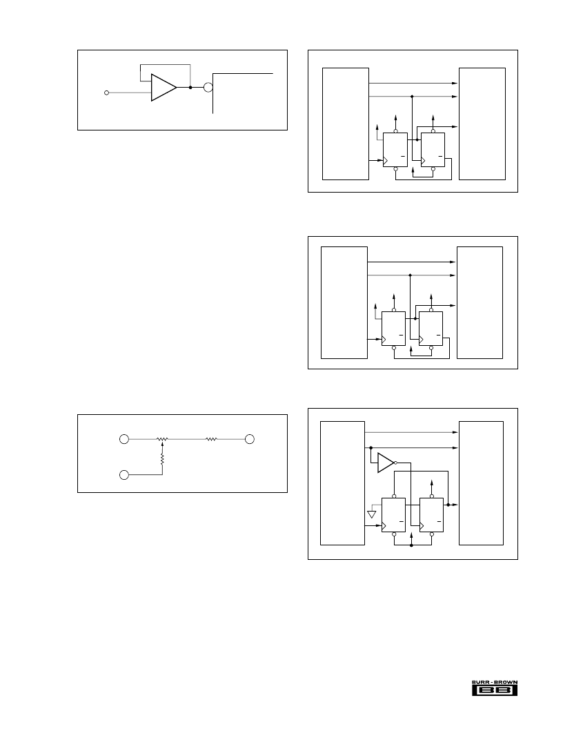
The PCM78 may be interfaced to many popular digital
signal processors, such as the TMS320, DSP56001, and the
DSP32. Suggested interface circuits for these processors are
shown in Figures 17-19.
S
D
Q
Q
Clk
R
S
D
Q
Q
Clk
R
+5V
+5V
Status
Clk Out
OUT1
S
Data In
ICK
ILD
NOTE: Set for
16-Bit external
ILD, ICK MSB
bit first
PCM78P
DSP32C
S
D
Q
Q
Clk
R
S
D
Q
Q
Clk
R
+5V
+5V
+5V
+5V
Status
Clk Out
OUT1
S
RXD
RXC
FSR
NOTE: FSM =
Bit Mode
PCM78P
DSP56001
FIGURE 18. PCM78 Interface to Motorola DSP56001 DSP
Processor.
FIGURE 19. PCM78 Interface to AT&T DSP16 & DSP32C
Processors.
1
PCM78
V
IN
–
+
OPA627
FIGURE 15. Buffer Amplifier for PCM78 Input.
S
D
Q
Q
Clk
R
S
D
Q
Q
Clk
R
+5V
+5V
+5V
+5V
Status
Clk Out
OUT1
S
DR
Clk R
FSR
NOTE: FSM = 1
PCM78P
TMS320C25/C30
FIGURE 17. PCM78 Interface to TMS320C25/C30 DSP
Processors.
相关PDF资料 |
PDF描述 |
|---|---|
| PCM78 | 16-Bit Audio ANALOG-TO-DIGITAL CONVERTER |
| PCM95G | GEHAEUSE WASSERD DECKEL GRAU 230X140X95 |
| BMP | MOTAGEPLATTE FUER 223256 268 311 323 |
| PCM95T | GEHAEUSE WASSERD DECK TRANSP 230X140X95 |
| PCNET | PCnet - PCnet Family Network Driver Installation Guide. Part 2 |
相关代理商/技术参数 |
参数描述 |
|---|---|
| PCM-79 | 功能描述:电线鉴定 Pre-Printed WM Card, Vinyl Cloth, .22" W RoHS:否 制造商:TE Connectivity / Q-Cees 产品:Labels and Signs 类型: 材料:Vinyl 颜色:Blue 宽度:0.625 in 长度:1 in |
| PCM-7T1 | 制造商:Panduit Corp 功能描述: |
| PCM-7T2 | 制造商:Panduit Corp 功能描述:Call vendor for pricing |
| PCM-8 | 功能描述:电线鉴定 1.5" VINYL CLOTH #8 RoHS:否 制造商:TE Connectivity / Q-Cees 产品:Labels and Signs 类型: 材料:Vinyl 颜色:Blue 宽度:0.625 in 长度:1 in |
| PCM-80 | 功能描述:电线鉴定 Pre-Printed WM Card, Vinyl Cloth, .22" W RoHS:否 制造商:TE Connectivity / Q-Cees 产品:Labels and Signs 类型: 材料:Vinyl 颜色:Blue 宽度:0.625 in 长度:1 in |
发布紧急采购,3分钟左右您将得到回复。