- 您现在的位置:买卖IC网 > PDF目录69043 > PDT003A0X43-SRZ (LINEAGE POWER LLC) 1-OUTPUT DC-DC REG PWR SUPPLY MODULE PDF资料下载
参数资料
| 型号: | PDT003A0X43-SRZ |
| 厂商: | LINEAGE POWER LLC |
| 元件分类: | 电源模块 |
| 英文描述: | 1-OUTPUT DC-DC REG PWR SUPPLY MODULE |
| 封装: | ROHS COMPLIANT PACKAGE-17 |
| 文件页数: | 9/38页 |
| 文件大小: | 662K |
| 代理商: | PDT003A0X43-SRZ |
第1页第2页第3页第4页第5页第6页第7页第8页当前第9页第10页第11页第12页第13页第14页第15页第16页第17页第18页第19页第20页第21页第22页第23页第24页第25页第26页第27页第28页第29页第30页第31页第32页第33页第34页第35页第36页第37页第38页
Preliminary Data Sheet
May 25, 2011
3A Digital Pico DLynxTM: Non-isolated DC-DC Power Modules
3 – 14.4Vdc input; 0.45Vdc to 5.5Vdc output; 3A output current
LINEAGE POWER
17
Dual Layout
Identical dimensions and pin layout of Analog and
Digital Pico DLynx modules permit migration from one
to the other without needing to change the layout. To
support this, 2 separate Trim Resistor locations have
to be provided in the layout. As shown in Fig. 46, for
the digital modules, the resistor is connected between
the TRIM pad and SGND and in the case of the analog
module it is connected between TRIM and GND.
Caution – For digital modules, do not connect
SIG_GND to GND elsewhere in the layout
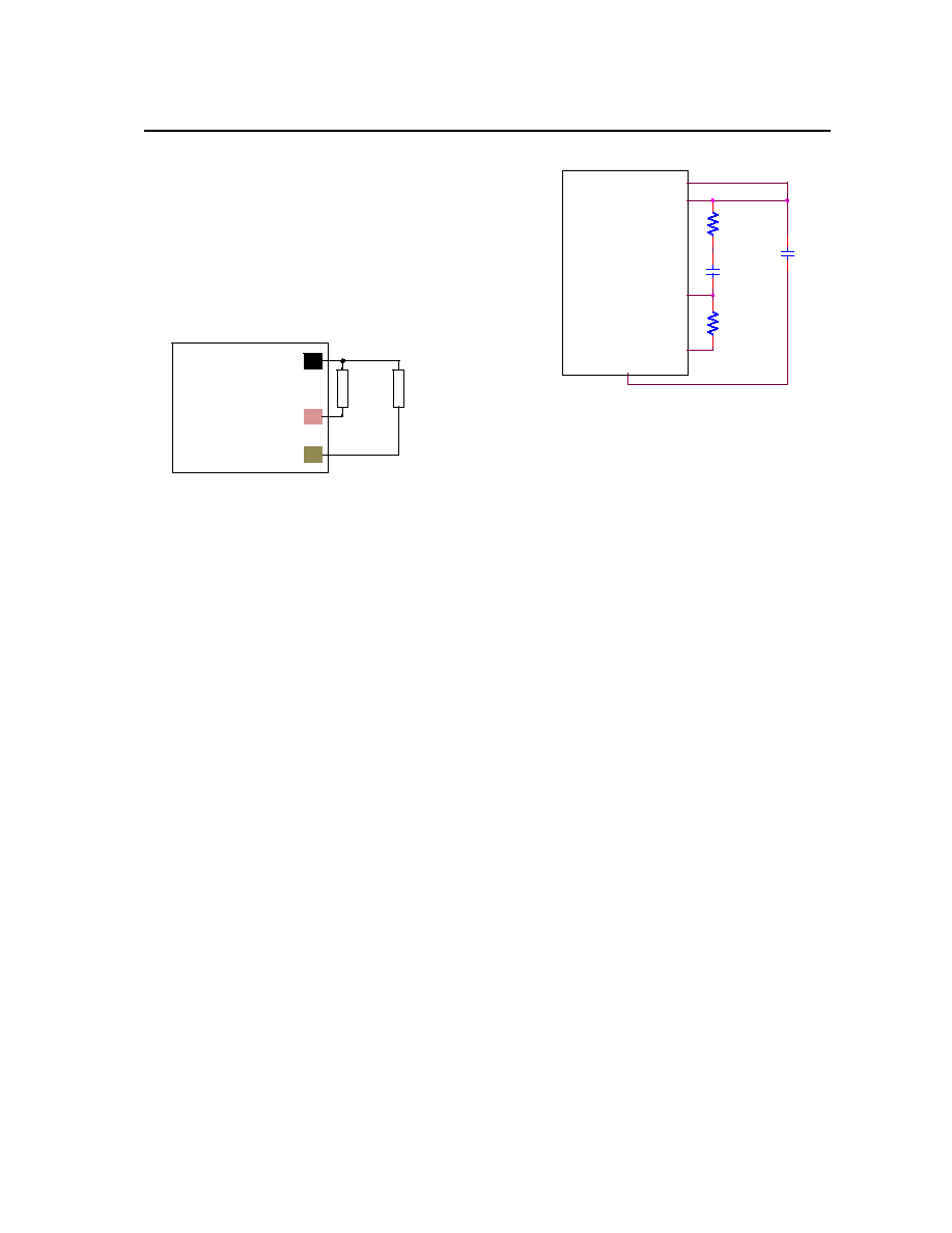
Figure 46. Connections to support either Analog
or Digital PicoDLynx on the same layout.
Tunable Loop
TM
The module has a feature that optimizes transient
response of the module called Tunable Loop
TM.
External capacitors are usually added to the output of
the module for two reasons: to reduce output ripple
and noise (see Figure 38) and to reduce output voltage
deviations from the steady-state value in the presence
of dynamic load current changes. Adding external
capacitance however affects the voltage control loop of
the module, typically causing the loop to slow down
with sluggish response. Larger values of external
capacitance could also cause the module to become
unstable.
The Tunable Loop
TM allows the user to externally
adjust the voltage control loop to match the filter
network connected to the output of the module. The
Tunable Loop
TM is implemented by connecting a series
R-C between the VS+ and TRIM pins of the module,
as shown in Fig. 47. This R-C allows the user to
externally adjust the voltage loop feedback
compensation of the module.
Figure. 47. Circuit diagram showing connection of
RTUME and CTUNE to tune the control loop of the
module.
Recommended values of RTUNE and CTUNE for different
output capacitor combinations are given in Table 2.
Table 2 shows the recommended values of RTUNE and
CTUNE for different values of ceramic output capacitors
up to 1000uF that might be needed for an application
to meet output ripple and noise requirements.
Selecting RTUNE and CTUNE according to Table 2 will
ensure stable operation of the module.
In applications with tight output voltage limits in the
presence of dynamic current loading, additional output
capacitance will be required. Table 3 lists
recommended values of RTUNE and CTUNE in order to
meet 2% output voltage deviation limits for some
common output voltages in the presence of a 6A to 3A
step change (50% of full load), with an input voltage of
12V.
Please contact your Lineage Power technical
representative to obtain more details of this feature as
well as for guidelines on how to select the right value
of external R-C to tune the module for best transient
performance and stable operation for other output
capacitance values or input voltages other than 12V.
Table 2. General recommended values of of RTUNE
and CTUNE for Vin=12V and various external
ceramic capacitor combinations.
TBD
Table 3. Recommended values of RTUNE and CTUNE
to obtain transient deviation of 2% of Vout for a 6A
step load with Vin=12V.
TBD
VS+
MODULE
SIG_GND
TRIM
VOUT
RTune
CTune
RTrim
CO
GND
MODULE
(PVX003 / PDT003)
Rtrim1
for
Digital
GND(Pin 7)
SIG_GND
TRIM
Rtrim2
for
Analog
相关PDF资料 |
PDF描述 |
|---|---|
| PE3336-52 | PHASE LOCKED LOOP, 3000 MHz, QCC44 |
| PE3336-53 | PHASE LOCKED LOOP, 3000 MHz, PQCC44 |
| PE3336-21 | PHASE LOCKED LOOP, 3000 MHz, PQCC44 |
| PE3336-00 | PHASE LOCKED LOOP, 3000 MHz, QCC44 |
| PE3336-22 | PHASE LOCKED LOOP, 3000 MHz, PQCC44 |
相关代理商/技术参数 |
参数描述 |
|---|---|
| PDT006A0X3-SRDZ | 功能描述:DC/DC转换器 3-14.4V 0.45-5.5Vout 6A smt, neg logic RoHS:否 制造商:Murata 产品: 输出功率: 输入电压范围:3.6 V to 5.5 V 输入电压(标称): 输出端数量:1 输出电压(通道 1):3.3 V 输出电流(通道 1):600 mA 输出电压(通道 2): 输出电流(通道 2): 安装风格:SMD/SMT 封装 / 箱体尺寸: |
| PDT006A0X3-SRZ | 功能描述:DC/DC转换器 3-14.4Vin .45-5.5V6A Neg Log SMT Digital RoHS:否 制造商:Murata 产品: 输出功率: 输入电压范围:3.6 V to 5.5 V 输入电压(标称): 输出端数量:1 输出电压(通道 1):3.3 V 输出电流(通道 1):600 mA 输出电压(通道 2): 输出电流(通道 2): 安装风格:SMD/SMT 封装 / 箱体尺寸: |
| PDT006A0X43-SRZ | 功能描述:DC/DC转换器 3-14.4V 0.45-5.5Vout 6A smt, pos logic RoHS:否 制造商:Murata 产品: 输出功率: 输入电压范围:3.6 V to 5.5 V 输入电压(标称): 输出端数量:1 输出电压(通道 1):3.3 V 输出电流(通道 1):600 mA 输出电压(通道 2): 输出电流(通道 2): 安装风格:SMD/SMT 封装 / 箱体尺寸: |
| PDT012A0X | 制造商:LINEAGEPOWER 制造商全称:LINEAGEPOWER 功能描述:12A Digital Pico DLynxTM: Non-Isolated DC-DC Power Modules |
| PDT012A0X3 | 制造商:LINEAGEPOWER 制造商全称:LINEAGEPOWER 功能描述:12A Digital Pico DLynxTM: Non-Isolated DC-DC Power Modules |
发布紧急采购,3分钟左右您将得到回复。