- 您现在的位置:买卖IC网 > PDF目录296800 > PEC16-2015F-N0024 (BOURNS INC) PDF资料下载
参数资料
| 型号: | PEC16-2015F-N0024 |
| 厂商: | BOURNS INC |
| 元件分类: | 编、解码器及复用、解复用 |
| 中文描述: | SINGLE, 2 CHANNELS, ROTARY OPTICAL POSITION ENCODER |
| 封装: | ROHS COMPLIANT, COMPACT PACKAGE-3 |
| 文件页数: | 1/3页 |
| 文件大小: | 342K |
| 代理商: | PEC16-2015F-N0024 |
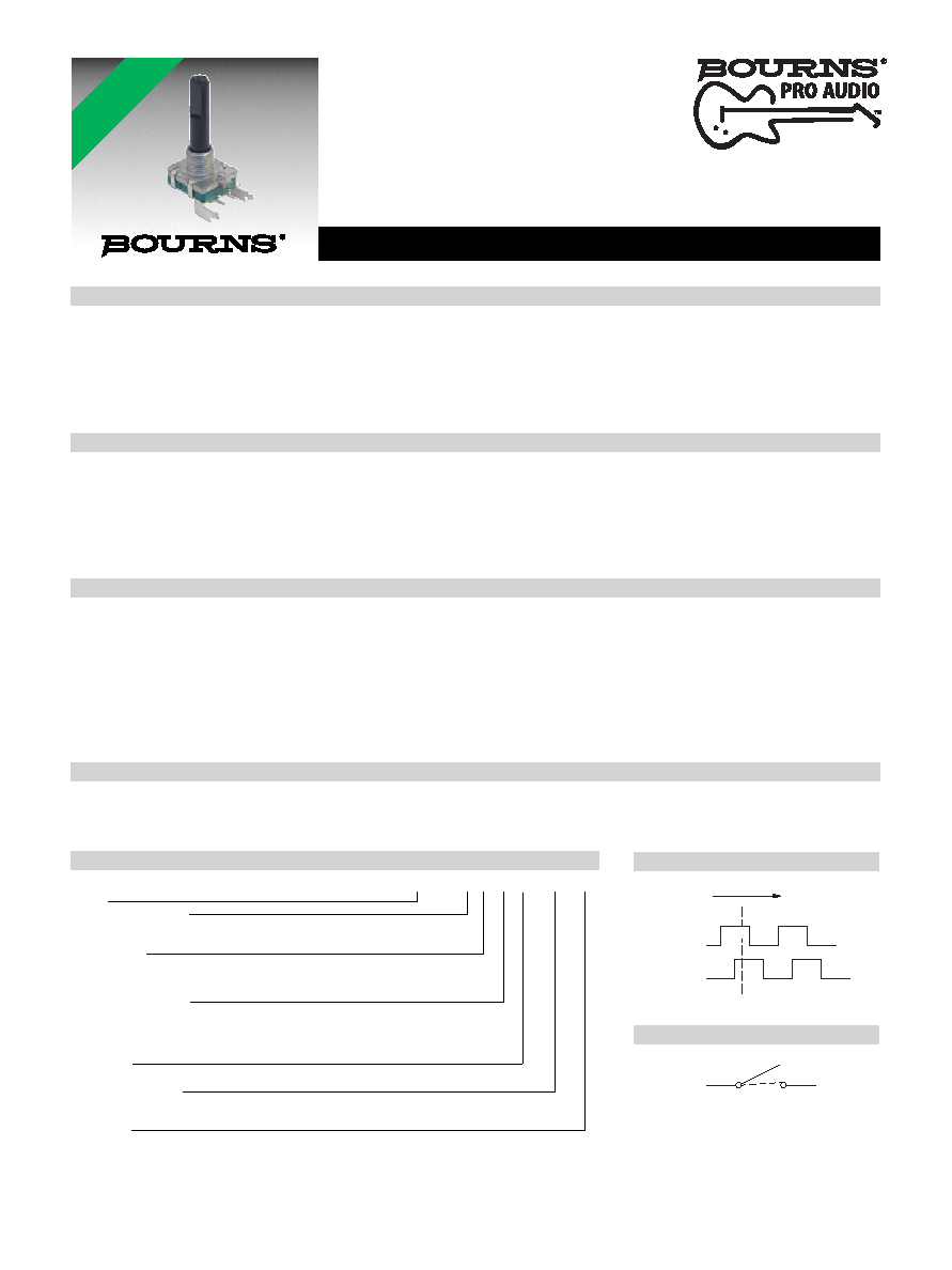
Features
■ Compact design, long life and high
reliability
■ Low cost compared to optical type
encoders
■ Available in a wide variety of congurations
to meet many user requirements
PEC16 - 16 mm Incremental Encoder
*RoHS Directive 2002/95/EC Jan 27, 2003 including Annex.
**Devices are tested using standard noise reduction lters. For optimum performance, designers should use noise reduction lters in their circuits.
Specications are subject to change without notice.
Customers should verify actual device performance in their specic applications.
How To Order
PEC16 - 4 0 20 F - S 0012
Model
Terminal Conguration
2 = PC Pin Vertical/Down Facing
4 = PC Horizontal/Rear Facing
Detent Option
0 = No Detents
1 = 12 Detents (available with 12 pulses only)
2 = 24 Detents (available with 24 pulses only)
Standard Shaft Length
15 = 15 mm
20 = 20.0 mm
25 = 25.0 mm1
30 = 30.0 mm1
Shaft Style
F = Insulated Flatted Shaft
Switch Conguration
S = Push Momentary Switch
N = No Switch
Resolution
0012 = 12 Pulses per 360 ° Rotation
0024 = 24 Pulses per 360 ° Rotation
1 Not available with switch
Electrical Characteristics
Output ..................................................................................................................................................................................................2-bit quadrature code
Closed Circuit Resistance .......................................................................................................................................................................... 3 ohms maximum
Contact Rating ................................................................................................................................................................................................ 1 mA @ 5 VDC
Insulation Resistance ........................................................................................................................................................................10 megohms @ 50 VDC
Dielectric Withstanding Voltage
Sea Level ................................................................................................................................................................................................. 50 VAC minimum
Electrical Travel..................................................................................................................................................................................................... Continuous
Contact Bounce (15 RPM)........................................................................................................................................................................5.0 ms. maximum**
RPM (Operating)............................................................................................................................................................................................ 100 maximum**
Environmental Characteristics
Operating Temperature Range ...................................................................................................................................... -30 °C to +70 °C (-22 °F to +158 °F)
Storage Temperature Range ......................................................................................................................................... -40 °C to +85 °C (-40 °F to +185 °F)
Humidity ............................................................................................................................................................... MIL-STD-202, Method 103B, Condition B
Vibration .......................................................................................................................................................................................................................... 30 G
Contact Bounce............................................................................................................................................... 10~55~10 Hz / 1 min. / Amplitude 1.5 mm
Shock ............................................................................................................................................................................................................................ 100 G
Rotational Life .................................................................................................................................................................................100,000 cycles minimum
Switch Life.........................................................................................................................................................................................20,000 cycles minimum
IP Rating ..........................................................................................................................................................................................................................IP 40
Mechanical Characteristics
Mechanical Angle .........................................................................................................................................................................................360 ° continuous
Torque
Running ................................................................................................................................................................... 30.6 to 204 g-cm (0.42 to 2.83 oz.-in)
Mounting..................................................................................................................................................................... 10.2 kgf. cm (8.83 lb.-in.) maximum
Shaft Side Load (Static)............................................................................................................................................................... 3.06 kgf (6.7 lbs.) minimum
Weight ............................................................................................................................................................................................ 8 gm (0.28 oz.) maximum
Terminals ................................................................................................................................................................................ Printed circuit board terminals
Soldering Condition
Wave Soldering..................................................................................... Sn95.5/Ag2.8/Cu0.7 solder with no-clean ux: 260 °C max. for 3-5 seconds
Hand Soldering.................................................................................................................................................................................Not recommended
Hardware ..................................................................................................................... One at washer and one mounting nut supplied with each encoder.
Switch Characteristics
Switch Type ................................................................................................................................................................... Contact Push ON Momentary SPST
Power Rating (Resistive Load) ..................................................................................................................................................................... 10 mA at 5 V DC
Switch Travel ............................................................................................................................................................................................... 0.5 +0.4/-0.3 mm
Switch Actuation Force ............................................................................................................................................... 360 +153/-102 gf (5 +2.1/-1.4 oz.-in.)
Quadrature Output Table
A Signal
CW
D
ON
OFF
B Signal
*RoHS
COMPLIANT
Switch Circuit
DE
相关PDF资料 |
PDF描述 |
|---|---|
| PEF22508E | DATACOM, PCM TRANSCEIVER, PBGA256 |
| PEF22554E | DATACOM, FRAMER, PBGA160 |
| PEF22554HT | DATACOM, FRAMER, PQFP144 |
| PES12-42S-N0024 | |
| PESD3V3V4UK,132 | 25 W, UNIDIRECTIONAL, 4 ELEMENT, SILICON, TVS DIODE |
相关代理商/技术参数 |
参数描述 |
|---|---|
| PEC16-2015F-S0012 | 功能描述:编码器 15MM SHAFT w/switch RoHS:否 制造商:Avago Technologies 产品:Optical Encoders 类型:Absolute 每转脉冲: 制动器数量: 通道数量:2 安装风格:Through Hole 端接类型:Solder Pin 输出: 轴类型: 带开关: 电源电压:5 V 工作温度范围:- 40 C to + 115 C |
| PEC16-2015F-S0024 | 功能描述:编码器 15MM SHAFT w/switch RoHS:否 制造商:Avago Technologies 产品:Optical Encoders 类型:Absolute 每转脉冲: 制动器数量: 通道数量:2 安装风格:Through Hole 端接类型:Solder Pin 输出: 轴类型: 带开关: 电源电压:5 V 工作温度范围:- 40 C to + 115 C |
| PEC16-2020F-N0012 | 制造商:BOURNS 制造商全称:Bourns Electronic Solutions 功能描述:16 mm Incremental Encoder |
| PEC16-2020F-N0024 | 制造商:BOURNS 制造商全称:Bourns Electronic Solutions 功能描述:16 mm Incremental Encoder |
| PEC16-2020F-S0012 | 功能描述:编码器 20MM SHAFT w/switch RoHS:否 制造商:Avago Technologies 产品:Optical Encoders 类型:Absolute 每转脉冲: 制动器数量: 通道数量:2 安装风格:Through Hole 端接类型:Solder Pin 输出: 轴类型: 带开关: 电源电压:5 V 工作温度范围:- 40 C to + 115 C |
发布紧急采购,3分钟左右您将得到回复。