- 您现在的位置:买卖IC网 > PDF目录69043 > PFS726EG (POWER INTEGRATIONS INC) POWER FACTOR CONTROLLER, 95 kHz SWITCHING FREQ-MAX, PZIP6 PDF资料下载
参数资料
| 型号: | PFS726EG |
| 厂商: | POWER INTEGRATIONS INC |
| 元件分类: | 稳压器 |
| 英文描述: | POWER FACTOR CONTROLLER, 95 kHz SWITCHING FREQ-MAX, PZIP6 |
| 封装: | HALOGEN FREE AND ROHS COMPLIANT, PLASTIC, SIP-7/6 |
| 文件页数: | 2/30页 |
| 文件大小: | 2647K |
| 代理商: | PFS726EG |
第1页当前第2页第3页第4页第5页第6页第7页第8页第9页第10页第11页第12页第13页第14页第15页第16页第17页第18页第19页第20页第21页第22页第23页第24页第25页第26页第27页第28页第29页第30页
Rev. A 11/09/10
10
PFS704-729EG
www.powerint.com
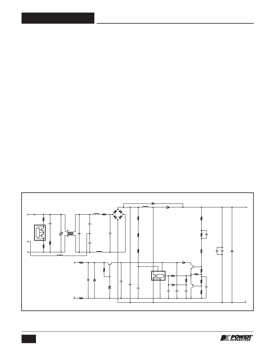
Application Example
A High Efficiency, 347 W, 380 VDC Universal Input PFC
The circuit shown in Figure 11 is designed using a PFS714EG
device from the HiperPFS family of integrated PFC controllers.
This design is rated for a continuous output power of 347 W
and provides a regulated output voltage of 380 VDC nominal
maintaining a high input power factor and overall efficiency from
light load to full load.
Fuse F1 provides protection to the circuit and isolates it from the
AC supply in case of a fault. Diode bridge BR1 rectifies the AC
input. Capacitors C3, C4, C5, C6 and C19 together with
inductors L1, L2, L3 and L4 form the EMI filter reducing the
common mode and differential mode noise. Resistors R1, R3
and CAPZero, IC U2 are required to discharge the EMI filter
capacitors once the circuit is disconnected. CAPZero
eliminates static losses in R1 and R2 by only connecting these
components across the input when AC is removed.
The boost converter stage consists of inductor L5, diode
rectifier D2 and the HiperPFS IC U1. This converter stage
works as a boost converter and controls the input current of the
power supply while simultaneously regulating the output DC
voltage. Diode D1 prevents a resonant build up of output
voltage at start-up by bypassing inductor L5 while simultaneously
charging output capacitor C15. Thermistor RT1 limits the inrush
input current of the circuit at start-up and prevents saturation of
L5. In most high-performance designs, a relay will be used to
bypass the thermistor after start-up to improve power supply
efficiency. Therefore efficiency measurement, that represents
the high performance configuration, the thermistors should be
shorted. Capacitors C14 and C21 are used for reducing the
loop length and area of the output circuit to reduce EMI and
overshoot of voltage across the drain and source of the
MOSFET inside U1 at each switching instant.
The PFS714EG IC requires a regulated supply of 12 V for
operation and must not exceed 13.4 V. Resistors R6, R16, R17,
Zener diode VR1, and transistor Q3 form a shunt regulator that
prevents the supply voltage to IC U1 from exceeding 12 V.
Capacitors C8, C18 and C20 filter the supply voltage and
provide decoupling to ensure reliable operation of IC U1. Diode
D5 prevents destruction of U1 if the auxiliary input is inadvertently
connected reverse polarity.
The rectified AC input voltage of the power supply is sensed by
IC U1 using resistors R4, R5 and R19. The capacitor C12 filters
any noise on this signal.
Divider network comprising of resistors R9, R10, R11, R12, R13,
and R14 are used to scale the output voltage and provide
feedback to IC U1. The circuit comprising of diode D4,
transistor Q1, Q2 and the resistors R12 and R13 form a non-
linear feedback circuit which improves the load transient
response by improving the response time of the PFC circuit.
Resistor R7, R8, R15, and capacitors C13 and C17 are required
for shaping the loop response of the feedback network. The
combination of resistor R8 and capacitor C13 provide a low
frequency zero and the resistor R15 and capacitor C13 form a
low frequency pole.
PI-6197-111110
N
E
L
R1
220 k
RT1
10
R6
100
C8
47
F
50 V
D5
DL4001
VR1
BZX84C12LT1G
Q3
MMBT4401LT1G
R16
100
R17
3.01 k
1%
R2
220 k
R18
10
2 W
L4
Ferrite Bead
R4
1.5 M
1%
R19
1.5 M
1%
R5
1 M
1%
L5
1.38 mH
BR1
GBU806
600 V
D1
1N5408
D4
1N4148
D3
BAV116
130 V
D2
STTH8S06D
L1
14 mH
C6
100 nF
275 VAC
C19
1
F
310 V
C5
680 pF
250 VAC
C7
1
F
400 V
R13
2.21 k
1%
R7
2 k
R12
2.21 k
1%
R10
1.6 M
1%
R11
732 k
1%
R9
1.5 M
1%
R15
160 k
C17
470 pF
100 V
C21
10 nF
1 kV
C14
10 nF
1 kV
C4
680 pF
250 VAC
C3
680 nF
275 VAC
F1
6.3 A
RV1
320 VAC
D
S
FB
VCC
V
G
DC
OUT
380 VDC
Auxiliary
Power
Supply
CONTROL
HiperPFS
U1
PFS714EG
C11
10 nF
50 V
C12
100 nF
50 V
C18
1
F
25 V
C13
4.7
F
25 V
C20
100 nF
50 V
Q1
MMBT4401
tO
D1
CAPZero
U2
CAP006DG
D2
L2
100
H
C16
100 nF
200 V
R14
57.6 k
1%
Q2
MMBT4403
L3
100
H
C15
270
F
450 V
*Optional Component
R8
3.01 k
1%
+
Figure 11. 347 W PFC using PFS714EG.
相关PDF资料 |
PDF描述 |
|---|---|
| PFS725EG | POWER FACTOR CONTROLLER, 95 kHz SWITCHING FREQ-MAX, PZIP6 |
| PFS712EG | POWER FACTOR CONTROLLER, 95 kHz SWITCHING FREQ-MAX, PZIP6 |
| PFS716EG | POWER FACTOR CONTROLLER, 95 kHz SWITCHING FREQ-MAX, PZIP6 |
| PFS708EG | POWER FACTOR CONTROLLER, 95 kHz SWITCHING FREQ-MAX, PZIP6 |
| PFS729EG | POWER FACTOR CONTROLLER, 95 kHz SWITCHING FREQ-MAX, PZIP6 |
相关代理商/技术参数 |
参数描述 |
|---|---|
| PFS727EG | 功能描述:功率因数校正 IC PFC w/ Pwr Mosfet 750 W MAX 180 VAC RoHS:否 制造商:Fairchild Semiconductor 开关频率:300 KHz 最大功率耗散: 最大工作温度:+ 125 C 安装风格:SMD/SMT 封装 / 箱体:SOIC-8 封装:Reel |
| PFS728EG | 功能描述:功率因数校正 IC PFC w/ Pwr Mosfet 900 W MAX 180 VAC RoHS:否 制造商:Fairchild Semiconductor 开关频率:300 KHz 最大功率耗散: 最大工作温度:+ 125 C 安装风格:SMD/SMT 封装 / 箱体:SOIC-8 封装:Reel |
| PFS729EG | 功能描述:功率因数校正 IC PFC w/ Pwr Mosfet 1000 W MAX 180 VAC RoHS:否 制造商:Fairchild Semiconductor 开关频率:300 KHz 最大功率耗散: 最大工作温度:+ 125 C 安装风格:SMD/SMT 封装 / 箱体:SOIC-8 封装:Reel |
| PFS7323L | 功能描述:功率因数校正 IC HiPwr PFC Controller 120 W peak power RoHS:否 制造商:Fairchild Semiconductor 开关频率:300 KHz 最大功率耗散: 最大工作温度:+ 125 C 安装风格:SMD/SMT 封装 / 箱体:SOIC-8 封装:Reel |
| PFS7324L | 功能描述:功率因数校正 IC HiPwr PFC Controller 150 W peak power RoHS:否 制造商:Fairchild Semiconductor 开关频率:300 KHz 最大功率耗散: 最大工作温度:+ 125 C 安装风格:SMD/SMT 封装 / 箱体:SOIC-8 封装:Reel |
发布紧急采购,3分钟左右您将得到回复。