- 您现在的位置:买卖IC网 > PDF目录69043 > PGA117AIPWRG4 (TEXAS INSTRUMENTS INC) SPECIALTY ANALOG CIRCUIT, PDSO20 PDF资料下载
参数资料
| 型号: | PGA117AIPWRG4 |
| 厂商: | TEXAS INSTRUMENTS INC |
| 元件分类: | 模拟信号调理 |
| 英文描述: | SPECIALTY ANALOG CIRCUIT, PDSO20 |
| 封装: | GREEN, PLASTIC, TSSOP-20 |
| 文件页数: | 13/47页 |
| 文件大小: | 1545K |
| 代理商: | PGA117AIPWRG4 |
第1页第2页第3页第4页第5页第6页第7页第8页第9页第10页第11页第12页当前第13页第14页第15页第16页第17页第18页第19页第20页第21页第22页第23页第24页第25页第26页第27页第28页第29页第30页第31页第32页第33页第34页第35页第36页第37页第38页第39页第40页第41页第42页第43页第44页第45页第46页第47页
SERIAL INTERFACE INFORMATION
1
2
3
4
5
6
7
8
9
10
11
12
13
14
15
16
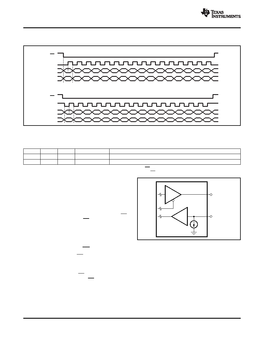
CS
SCLK
DIN
DOUT
SPIMode0,0(CPOL=0,CPHA=0)
CS
SCLK
DIN
DOUT
1
2
3
4
5
6
7
8
9
10
11
12
13
14
15
16
SPIMode1,1(CPOL=1,CPHA=1)
SERIAL DIGITAL INTERFACE: SPI MODES
10 A
m
PGA116
PGA117
DOUT
DIN
SBOS424B – MARCH 2008 – REVISED SEPTEMBER 2008 ............................................................................................................................................ www.ti.com
Figure 58. SPI Mode 0,0 and Mode 1,1
Table 2. SPI Mode Setting Description
MODE
CPOL
CPHA
CPOL DESCRIPTION
CPHA DESCRIPTION
0, 0
0
0(1)
Clock idles low
Data are read on the rising edge of clock. Data change on the falling edge of clock.
1, 1
1
1(2)
Clock idles high
Data are read on the rising edge of clock. Data change on the falling edge of clock.
(1)
CPHA = 0 means sample on first clock edge (rising or falling) after a valid CS.
(2)
CPHA = 1 means sample on second clock edge (rising or falling) after a valid CS.
The PGA uses a standard serial peripheral interface
(SPI). Both SPI Mode 0,0 and Mode 1,1 are
supported, as shown in Figure 58 and described in
If there are not even-numbered increments of 16
clocks (that is, 16, 32, 64, and so forth) between CS
going low (falling edge) and CS going high (rising
edge), the device takes no action. This condition
provides reliable serial communication. Furthermore,
this condition also provides a way to quickly reset the
SPI interface to a known starting condition for data
synchronization.
Transmitted
data
are
latched
Figure 59. Digital I/O Structure—PGA116/PGA117
internally on the rising edge of CS.
On the PGA116/PGA117, CS, DIN, and SCLK are
Schmitt-triggered CMOS logic inputs. DIN has a weak
internal
pull-down
to
support
daisy-chain
communications on the PGA116/PGA117. DOUT is a
CMOS logic output. When CS is high, the state of
DOUT is high-impedance. When CS is low, DOUT is
driven as illustrated in Figure 59.
20
Copyright 2008, Texas Instruments Incorporated
相关PDF资料 |
PDF描述 |
|---|---|
| PGA112AIDGST | SPECIALTY ANALOG CIRCUIT, PDSO10 |
| PGA112AIDGSTG4 | SPECIALTY ANALOG CIRCUIT, PDSO10 |
| PGDS-50-O-K/T-L | 1-OUTPUT 50 W DC-DC REG PWR SUPPLY MODULE |
| PGDS-50-N-K/T | 1-OUTPUT 50 W DC-DC REG PWR SUPPLY MODULE |
| PGDS-50-N-K/S-L | 1-OUTPUT 50 W DC-DC REG PWR SUPPLY MODULE |
相关代理商/技术参数 |
参数描述 |
|---|---|
| PGA-120-AH3-S-TG | 制造商:3M Electronic Products Division 功能描述: |
| PGA120M004B1-1315BLU | 制造商:FCI 功能描述: |
| PGA1215314B113D8F | 制造商:MCKENZIE 功能描述:SOCKET |
| PGA1215314B1-13D8F | 制造商:MCKENZIE 功能描述:SOCKET |
| PGA121H003B1-1312R | 功能描述:IC 与器件插座 121H PGA 13X13 1312 RoHS:否 制造商:Molex 产品:LGA Sockets 节距:1.02 mm 排数: 位置/触点数量:2011 触点电镀:Gold 安装风格:SMD/SMT 端接类型:Solder 插座/封装类型:LGA 2011 工作温度范围:- 40 C to + 100 C |
发布紧急采购,3分钟左右您将得到回复。