参数资料
| 型号: | PI3CH1010QE |
| 厂商: | Pericom |
| 文件页数: | 3/6页 |
| 文件大小: | 0K |
| 描述: | IC 10-CH SWITCH 2-PORT 24-QSOP |
| 标准包装: | 55 |
| 类型: | 总线开关 |
| 电路: | 10 x 1:1 |
| 独立电路: | 1 |
| 电压电源: | 单电源 |
| 工作温度: | -40°C ~ 85°C |
| 安装类型: | 表面贴装 |
| 封装/外壳: | 24-SSOP(0.154",3.90mm 宽) |
| 供应商设备封装: | 24-QSOP |
| 包装: | 管件 |
|||||||||||||||||||||||||||||||||||||||||||||||||||||||||||||||||||||||||||||||||||||||||||||||||||||||||||||||||||||||||||||||||||||||||||||||||||||||||
||||||||||||||||||||||||||||||||||||||||||||||||||||||||||||||||||||||||||||||||||||||||||||||||||||||||||||||||||||||||||||||||||||||||||||||||||||||||||||||||||||||||||||||
2013-08-0001
PT0470-1
08/15/13
3
PI3CH1010
10-Bit Bus Switch, Enable Low
1.8V/2.5V/3.3V, High-Bandwidth, Hot Plug
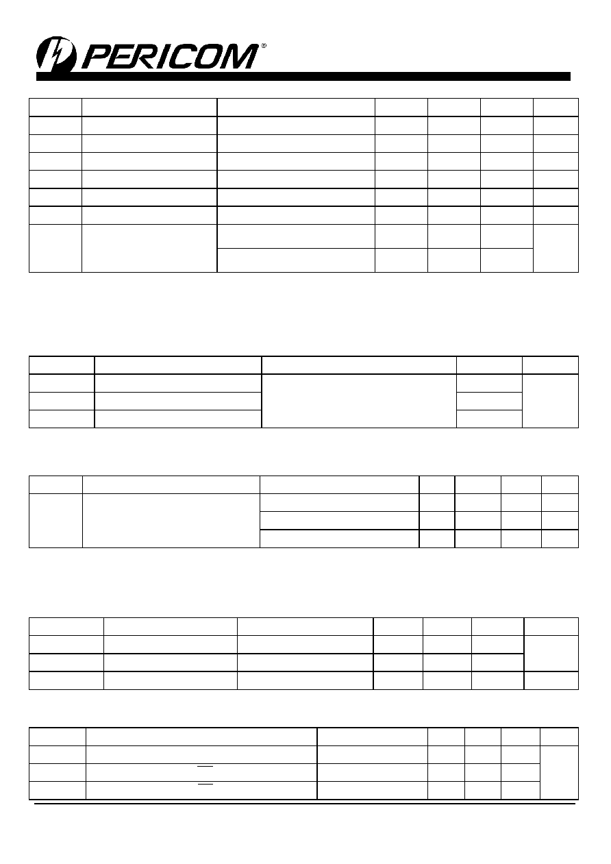
1.8V supply (Over operating range, TA = -40 to +85C, VCC=1.8V±10%, unless otherwise noted)
Symbol
Description
Test Conditions
(1)
Min
Typ
(2)
Max
Unit
VIH
Control Input HIGH Voltage
Guaranteed Logic HIGH Level
1.2
-
VCC+0.3
V
VIL
Control Input LOW Voltage
Guaranteed Logic LOW Level
-0.3
-
0.6
V
VIK
Clamp Diode Voltage
VCC = Min., IIN = -18mA
-
-0.7
-1.8
V
IIH
Input HIGH Current
VCC = Max., VIN = VCC
-
±1
μA
IIL
Input Low Current
VCC = Max., VIN = GND
-
±1
μA
IOZH
High-Impedance Current
0 ≤ A, B ≤ V
CC
-
±1
μA
RON
Switch On-Resistance
(3)
VCC = Min., VIN = 0.0V
ION = -48mA
-
4
8
VCC = Min., VIN = 1.6V
ION = -15mA
-
10
18
Notes:
1. For Max. or Min. conditions, use appropriate value specified under Electrical Characteristics for the applicable device type.
2. Typical values are at VCC = 1.8V, TA = 25°C ambient and maximum loading.
3. Measured by the voltage drop between A and B pin at indicated current through the switch. On-Resistance is determined
by the lower of the voltages on the two (A, B) pins.
Capacitance (TA = 25C, f=1MHz)
Symbol
(1)
Description
Test Conditions
Typ
(2)
Unit
CIN
Input Capacitance
VIN = 0V
2.0
pF
COFF
A/B Capacitance, Switch Off
3.5
CON
A/B Capacitance, Switch On
7.0
Note:
1. These parameters are determined by device characterization but are not production tested
Power Supply Characteristics
Symbol
Description
Test Conditions
(1)
Min
Typ
Max
Unit
ICC
Quiescent Power Supply Current
VCC = 3.6V, VIN = GND or VCC
-
0.2
0.5
mA
VCC = 2.5V, VIN = GND or VCC
-
0.15
0.4
mA
VCC = 1.8V, VIN = GND or VCC
-
0.8
1.5
mA
Note:
1. For Max. or Min. conditions, use appropriate value specified under Electrical Characteristics for the applicable device.
2. Typical values are at +25°C ambient
Dynamic Electrical Characteristics
(Over Operating Range, TA = -40 ~ +85C, VCC=3.3V±10%)
Symbol
Description
Test Conditions
Min
Typ
Max
Unit
XTALK
Crosstalk
10MHz
-
-60
-
dB
OIRR
Off-Isolation
10MHz
-
-60
-
BW
-3dB Bandwidth
See test Diagram
-
500
-
MHz
Switch Characteristics
Over 3.3V Operating Range
Symbol
Description
Test Conditions
(1)
Min
Typ
Max
Unit
tPLH, tPHL
Propagation Delay
(2, 3) Ax to Bx, Bx to Ax
See test Diagram
-
0.3
ns
tPZH, tPZL
Enable Time EN to Ax or Bx
See test Diagram
1.5
-
9.0
tPHZ, tPLZ
Disable Time EN to Ax or Bx
See test Diagram
1.5
-
9.0
相关PDF资料 |
PDF描述 |
|---|---|
| PI3CH200LE | IC 2-CH SWITCH 2-PORT 8-TSSOP |
| PI3CH281LE | IC 4:1 MUX/DEMUX 2CH 3ST 16TSSOP |
| PI3CH360QE | IC 2:1 MUX/DEMUX 3CH 3ST 16-QSOP |
| PI3CH400QE | IC 4-CH SWITCH 2-PORT 16-QSOP |
| PI3CH401QE | IC 4-CH SWITCH 2-PORT 16-QSOP |
相关代理商/技术参数 |
参数描述 |
|---|---|
| PI3CH1010QEX | 功能描述:数字总线开关 IC Lo Vltg 5Ohm 10Ch RoHS:否 制造商:Texas Instruments 开关数量:24 传播延迟时间:0.25 ns 最大工作温度:+ 85 C 最小工作温度:- 40 C 封装 / 箱体:TSSOP-56 封装:Reel |
| PI3CH200 | 制造商:PERICOM 制造商全称:Pericom Semiconductor Corporation 功能描述:Low Voltage, 5Ω, 2-Channel 2-Port NanoSwitch? |
| PI3CH200L | 制造商:PERICOM 制造商全称:Pericom Semiconductor Corporation 功能描述:Low Voltage, 5Ω, 2-Channel 2-Port NanoSwitch? |
| PI3CH200LE | 功能描述:数字总线开关 IC Lo Vltg 5Ohm 2Ch RoHS:否 制造商:Texas Instruments 开关数量:24 传播延迟时间:0.25 ns 最大工作温度:+ 85 C 最小工作温度:- 40 C 封装 / 箱体:TSSOP-56 封装:Reel |
| PI3CH200LEX | 功能描述:数字总线开关 IC Lo Vltg 5Ohm 2Ch RoHS:否 制造商:Texas Instruments 开关数量:24 传播延迟时间:0.25 ns 最大工作温度:+ 85 C 最小工作温度:- 40 C 封装 / 箱体:TSSOP-56 封装:Reel |
发布紧急采购,3分钟左右您将得到回复。