参数资料
| 型号: | PI5C3305UEX |
| 厂商: | Pericom |
| 文件页数: | 2/6页 |
| 文件大小: | 0K |
| 描述: | IC 2-BIT BUS SWITCH 8-MSOP |
| 标准包装: | 4,000 |
| 类型: | 总线开关 |
| 电路: | 1 x 1:1 |
| 独立电路: | 2 |
| 电压电源: | 单电源 |
| 电源电压: | 4 V ~ 5.5 V |
| 工作温度: | -40°C ~ 85°C |
| 安装类型: | 表面贴装 |
| 封装/外壳: | 8-TSSOP,8-MSOP(0.118",3.00mm 宽) |
| 供应商设备封装: | 8-MSOP |
| 包装: | 带卷 (TR) |
2
PS8331I
12/02/09
PI5C3305
2-Bit Bus Switch with Individual Enables
Storage Temperature ..........................................................–65°C to +150°C
Ambient Temperature with Power Applied .........................–40°C to +85°C
Supply Voltage to Ground Potential .....................................–0.5V to +7.0V
DC Input Voltage ..................................................................–0.5V to +7.0V
DC Output Current.............................................................................120mA
Power Dissipation .................................................................................0.5W
Note:
Stresses greater than those listed under MAXIMUM
RATINGS may cause permanent damage to the
device. This is a stress rating only and functional operation
of the device at these or any other conditions above those
indicated in the operational sections of this specication is
not implied. Exposure to absolute maximum rating condi-
tions for extended periods may affect reliability.
Maximum Ratings
(Above which the useful life may be impaired. For user guidelines, not tested.)
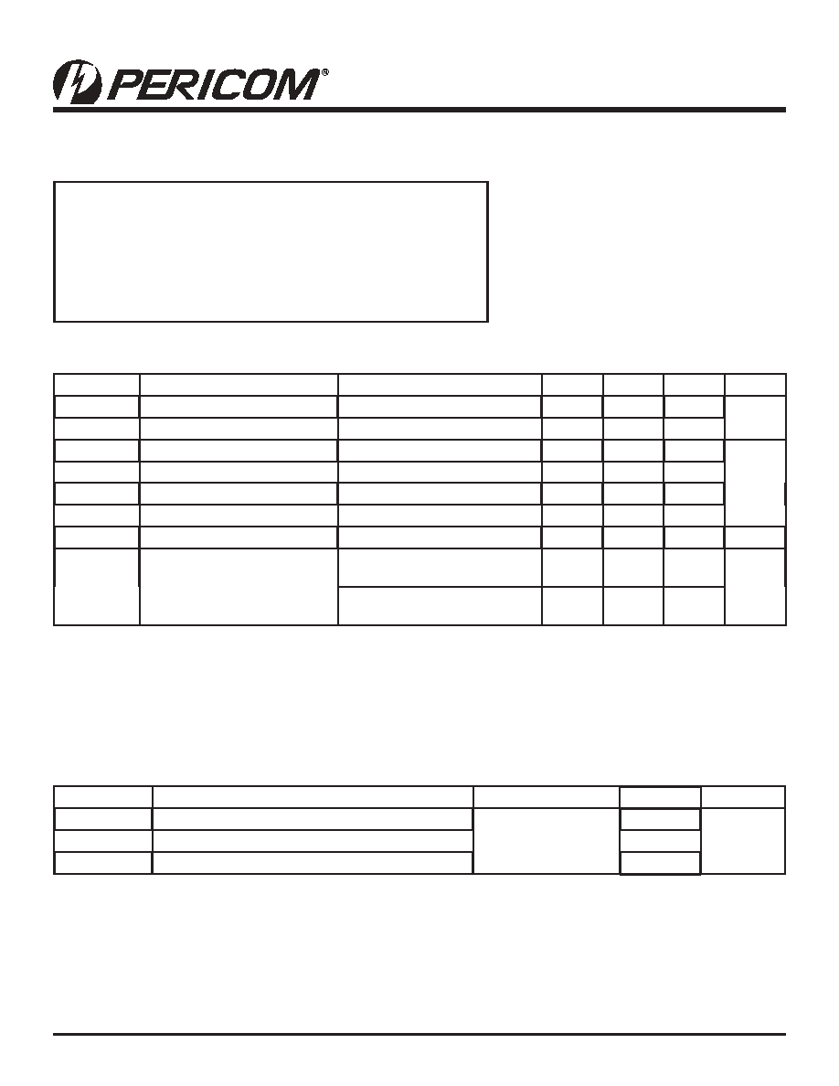
DC Electrical Characteristics (Over the Operating Range, TA = –40°C to +85°C, VCC = 4V to 5.5V)
Parameters
Description
Test Conditions(1)
Min.
Typ(2)
Max.
Units
VIH
Input HIGH Voltage
Guaranteed Logic HIGH Level
2.0
V
VIL
Input LOW Voltage
Guaranteed Logic LOW Level
–0.5
0.8
IIH
Input HIGH Current
VCC = Max., VIN = VCC
±1
μA
IIL
Input LOW Current
VCC = Max., VIN = GND
±1
IOZ
High Impedance Output Current
0 ≤ A, B ≤ VCC
±1
ION
Low Impedance Output Current
0 ≤ A, B ≤ VCC
±1
VH
Input Hysteresis at Control Pins
250
mV
RON
Switch On-Resistance(3)
VCC = 4.5V, VIN = 0.0V,
ION = 30mA or 64mA
47
Ω
VCC = 4.5V, VIN = 2.4V,
ION = –15mA
815
Capacitance (TA = 25°C, f = 1 MHz)
Parameters(1)
Description
Test Conditions
Typ.(4)
Units
CIN
Input Capacitance
VIN = 0V
3
pF
COFF
A/B Capacitance, Switch Off
5
CON
A/B Capacitance, Switch On
10
Notes:
1.
For Max. or Min. conditions, use appropriate value specied under Electrical Characteristics for the applicable device type.
2.
Typical values are at VCC = 5.0V, TA = 25°C ambient and maximum loading.
3.
Measured by the voltage drop between A and B pin at indicated current through the switch. On-Resistance is determined
by the lower of the voltages on the two (A, B) pins.
Notes:
1.
This parameter is determined by device characterization but is not production tested.
09-0007
相关PDF资料 |
PDF描述 |
|---|---|
| PI5C3306LE | IC 2-BIT BUS SWITCH 8-TSSOP |
| PI5C3309UEX | IC 3:1 MUX/DEMUX BUS SW 8-MSOP |
| PI5C3383QE | IC 5-BIT 4-PORT BUS SW 24-QSOP |
| PI5C3384Q | IC 10BIT 2PORT BUS SWITCH 24QSOP |
| PI5C3400S | IC 4BIT 4PORT BUS SWITCH 24SOIC |
相关代理商/技术参数 |
参数描述 |
|---|---|
| PI5C3305UX | 制造商:PERICOM 制造商全称:Pericom Semiconductor Corporation 功能描述:2-Bit Bus Switch with Individual Enables |
| PI5C3306 | 制造商:PERICOM 制造商全称:Pericom Semiconductor Corporation 功能描述:2-Bit Bus Switch with Active Low Enables |
| PI5C3306CD | 制造商:未知厂家 制造商全称:未知厂家 功能描述:Digital Switch | 2-Bit Bus Switch w/dual side undershoot protection |
| PI5C3306L | 制造商:PERICOM 制造商全称:Pericom Semiconductor Corporation 功能描述:2-Bit Bus Switch with Active Low Enables |
| PI5C3306LE | 功能描述:数字总线开关 IC 2Bit Bus Switch 2-Port RoHS:否 制造商:Texas Instruments 开关数量:24 传播延迟时间:0.25 ns 最大工作温度:+ 85 C 最小工作温度:- 40 C 封装 / 箱体:TSSOP-56 封装:Reel |
发布紧急采购,3分钟左右您将得到回复。