- 您现在的位置:买卖IC网 > PDF目录11639 > PIC10F200-E/MC (Microchip Technology)IC PIC MCU FLASH 256X12 8DFN PDF资料下载
参数资料
| 型号: | PIC10F200-E/MC |
| 厂商: | Microchip Technology |
| 文件页数: | 14/94页 |
| 文件大小: | 0K |
| 描述: | IC PIC MCU FLASH 256X12 8DFN |
| 标准包装: | 150 |
| 系列: | PIC® 10F |
| 核心处理器: | PIC |
| 芯体尺寸: | 8-位 |
| 速度: | 4MHz |
| 外围设备: | POR,WDT |
| 输入/输出数: | 3 |
| 程序存储器容量: | 384B(256 x 12) |
| 程序存储器类型: | 闪存 |
| RAM 容量: | 16 x 8 |
| 电压 - 电源 (Vcc/Vdd): | 2 V ~ 5.5 V |
| 振荡器型: | 内部 |
| 工作温度: | -40°C ~ 125°C |
| 封装/外壳: | 8-VFDFN 裸露焊盘 |
| 包装: | 管件 |
| 配用: | AC164334-ND - MODULE SOCKET FOR 8L 2X3MM DFN AC163020-2-ND - ADAPTER PROGRAM PIC10F 2X3 DFN |
第1页第2页第3页第4页第5页第6页第7页第8页第9页第10页第11页第12页第13页当前第14页第15页第16页第17页第18页第19页第20页第21页第22页第23页第24页第25页第26页第27页第28页第29页第30页第31页第32页第33页第34页第35页第36页第37页第38页第39页第40页第41页第42页第43页第44页第45页第46页第47页第48页第49页第50页第51页第52页第53页第54页第55页第56页第57页第58页第59页第60页第61页第62页第63页第64页第65页第66页第67页第68页第69页第70页第71页第72页第73页第74页第75页第76页第77页第78页第79页第80页第81页第82页第83页第84页第85页第86页第87页第88页第89页第90页第91页第92页第93页第94页
2007 Microchip Technology Inc.
DS41239D-page 19
PIC10F200/202/204/206
4.4
STATUS Register
This register contains the arithmetic status of the ALU,
the Reset status and the page preselect bit.
The STATUS register can be the destination for any
instruction, as with any other register. If the STATUS
register is the destination for an instruction that affects
the Z, DC or C bits, then the write to these three bits is
disabled. These bits are set or cleared according to the
device logic. Furthermore, the TO and PD bits are not
writable. Therefore, the result of an instruction with the
STATUS register as destination may be different than
intended.
For example, CLRF STATUS, will clear the upper three
bits and set the Z bit. This leaves the STATUS register
as 000u u1uu (where u = unchanged).
Therefore, it is recommended that only BCF, BSF and
MOVWF instructions be used to alter the STATUS regis-
ter. These instructions do not affect the Z, DC or C bits
from the STATUS register. For other instructions which
do affect Status bits, see Section 10.0 “Instruction
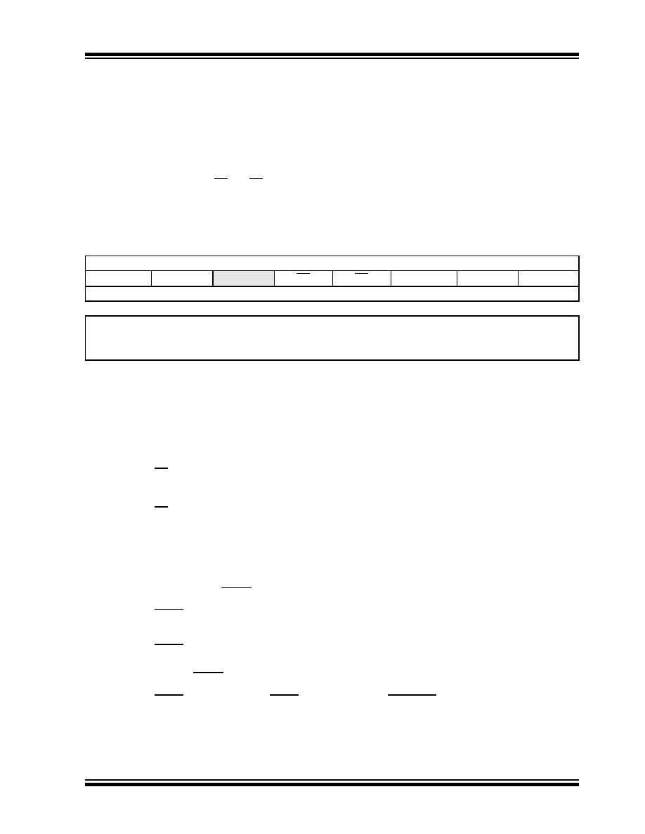
REGISTER 4-1:
STATUS REGISTER
R/W-0
R-1
R/W-x
GPWUF
CWUF(1)
—TO
PD
ZDC
C
bit 7
bit 0
Legend:
R = Readable bit
W = Writable bit
U = Unimplemented bit, read as ‘0’
-n = Value at POR
‘1’ = Bit is set
‘0’ = Bit is cleared
x = Bit is unknown
bit 7
GPWUF: GPIO Reset bit
1 = Reset due to wake-up from Sleep on pin change
0 = After power-up or other Reset
bit 6
CWUF: Comparator Wake-up on Change Flag bit(1)
1 = Reset due to wake-up from Sleep on comparator change
0 = After power-up or other Reset conditions.
bit 5
Reserved: Do not use. Use of this bit may affect upward compatibility with future products.
bit 4
TO: Time-out bit
1 = After power-up, CLRWDT instruction or SLEEP instruction
0 = A WDT time-out occurred
bit 3
PD: Power-Down bit
1 = After power-up or by the CLRWDT instruction
0 = By execution of the SLEEP instruction
bit 2
Z: Zero bit
1 = The result of an arithmetic or logic operation is zero
0 = The result of an arithmetic or logic operation is not zero
bit 1
DC: Digit Carry/Borrow bit (for ADDWF and SUBWF instructions)
ADDWF
:
1 = A carry from the 4th low-order bit of the result occurred
0 = A carry from the 4th low-order bit of the result did not occur
SUBWF
:
1 = A borrow from the 4th low-order bit of the result did not occur
0 = A borrow from the 4th low-order bit of the result occurred
bit 0
C: Carry/Borrow bit (for ADDWF, SUBWF and RRF, RLF instructions)
ADDWF
:
SUBWF
:
RRF
or RLF:
1 = A carry occurred
1 = A borrow did not occur Load bit with LSb or MSb, respectively
0 = A carry did not occur
0 = A borrow occurred
Note 1:
This bit is used on the PIC10F204/206. For code compatibility do not use this bit on the PIC10F200/202.
相关PDF资料 |
PDF描述 |
|---|---|
| VI-J40-IY-F1 | CONVERTER MOD DC/DC 5V 50W |
| PIC16F54T-I/SO | IC MCU FLASH 512X12 18SOIC |
| VI-BNF-CU-S | CONVERTER MOD DC/DC 72V 200W |
| MS27505E17B55S | CONN RCPT 55POS BOX MNT W/SCKT |
| VI-BND-CU-S | CONVERTER MOD DC/DC 85V 200W |
相关代理商/技术参数 |
参数描述 |
|---|---|
| PIC10F200-I/MC | 功能描述:8位微控制器 -MCU 0.375KB Fl 16B RAM RoHS:否 制造商:Silicon Labs 核心:8051 处理器系列:C8051F39x 数据总线宽度:8 bit 最大时钟频率:50 MHz 程序存储器大小:16 KB 数据 RAM 大小:1 KB 片上 ADC:Yes 工作电源电压:1.8 V to 3.6 V 工作温度范围:- 40 C to + 105 C 封装 / 箱体:QFN-20 安装风格:SMD/SMT |
| PIC10F200-I/OT | 制造商:Microchip Technology Inc 功能描述:MCU 8BIT PIC10 RISC 384BYTE FL - Bulk |
| PIC10F200-I/OT153 | 制造商:Microchip Technology Inc 功能描述: |
| PIC10F200-I/P | 功能描述:8位微控制器 -MCU .375kBF 16RM 4I/O Ind Temp PDIP8 RoHS:否 制造商:Silicon Labs 核心:8051 处理器系列:C8051F39x 数据总线宽度:8 bit 最大时钟频率:50 MHz 程序存储器大小:16 KB 数据 RAM 大小:1 KB 片上 ADC:Yes 工作电源电压:1.8 V to 3.6 V 工作温度范围:- 40 C to + 105 C 封装 / 箱体:QFN-20 安装风格:SMD/SMT |
| PIC10F200-I/P | 制造商:Microchip Technology Inc 功能描述:IC 8BIT FLASH MCU 10F200 DIP8 |
发布紧急采购,3分钟左右您将得到回复。